Bud Uzes (1934 - 2006)
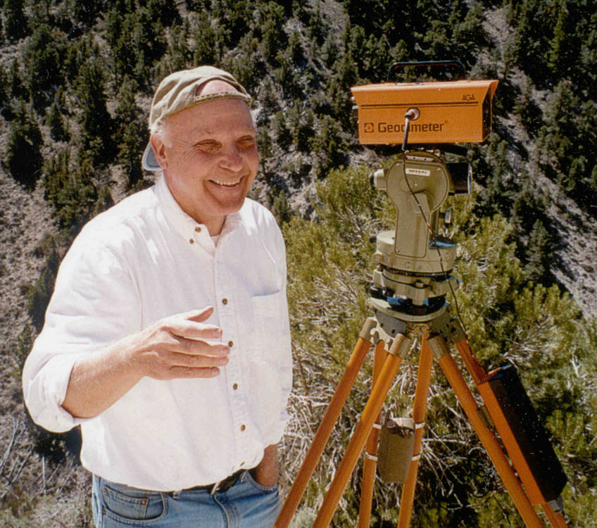
Bud Uzes Doing What He Loved Most - Surveying in a Great Setting on Nice Day
Bud's Surveying History
Bud operated a consulting and expert witness business from 1987 thru 2006, focused on surveying and complex boundary determinations. Prior to that Bud worked 33 year for the California State Lands Division where he was head of the surveying and boundary determination section. His strong interest in all aspects of surveying history included the techniques, education, instructions, laws and technology relating to surveying.
Bud consulted and served as an expert witness in surveying and boundary disputes in over one hundred cases, including twice testifying in proceedings before Special Masters of the U.S. Supreme Court. One of the cases involved the California-Nevada state boundary that resulted from discrepancies Bud uncovered while researching the first edition of Chaining the Land.
Bud served six years as the first president of the Surveyors Historical Society. He had a large collection of antique surveying instruments plus an extraordinary collection of antiquarian surveying books dating back to the 16th century. Bud authored Chaining the Land (two editions), The Illustrated Price Guide to Antique Surveying Instruments and Books, and was a contributing author to several editions of Browns Boundary Control and Legal Principles.
Chaining the Land and The Price Guide
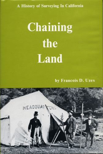
The First Edition of Chaining the Land, published in 1977. 319 pages. I was a senior in High School when Bud wrote this, and did not really focus much on what Bud was doing. But I do remember him telling me excitedly one night that the California - Nevada border was in the wrong place, and that was mildly interesting to me given that Nevada allowed gambling.
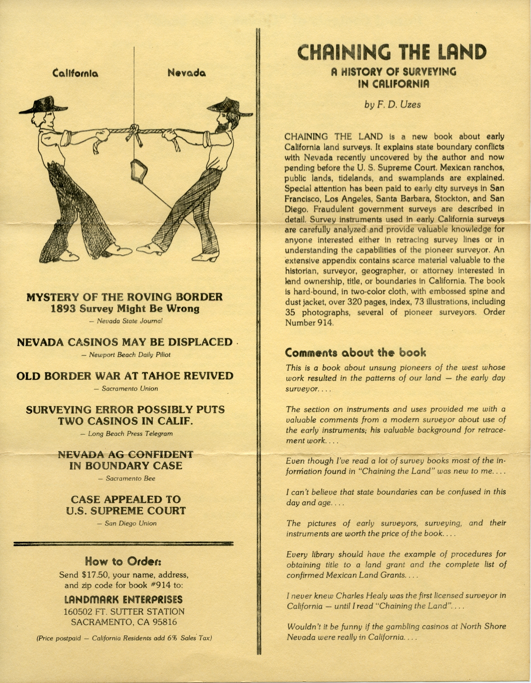
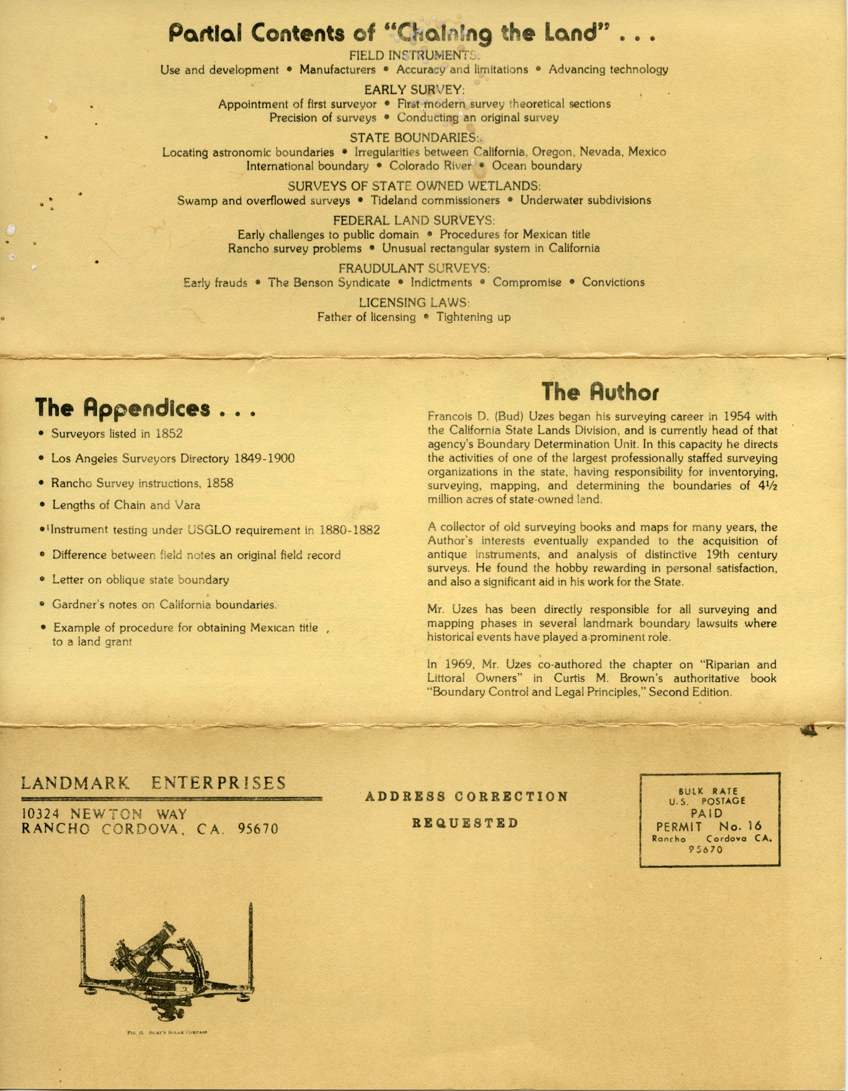
I found an old 1977 flyer that describes the contents of the book. Front Side - Back Side.
I recently uncovered a small stash of First Editions in brand new condition that I'm selling for $50 each. Send me an email if you're interested.
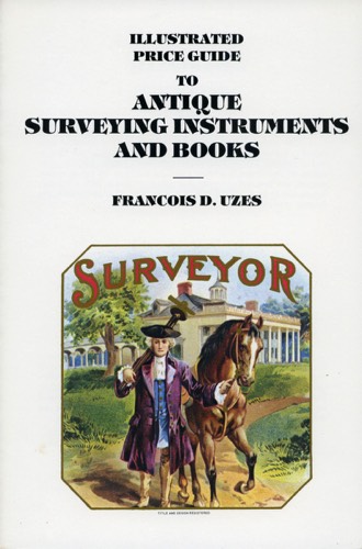
Bud published the paperback Illustrated Price Guide in 1980. I was a junior in college, and really didn't care about this publication either at the time, other than Bud made me proofread it several times.
The Price Guide resonated with me a bit later, however. After looking it over several times, I concluded that I could create The Compleat Surveyor business. While the price were out of date, the guide gave me a decent understanding about what I should be looking for as I scoured the country looking for old instruments and books.
I scanned in my personal copy of the Price Guide. Download Bud's 1980 Illustrated Price Guide here.
IMPORTANT - This Download is for your private use only. Please do not copy or distribute the download, or post any part of the book on an online social media account. Thanks.
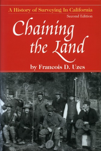
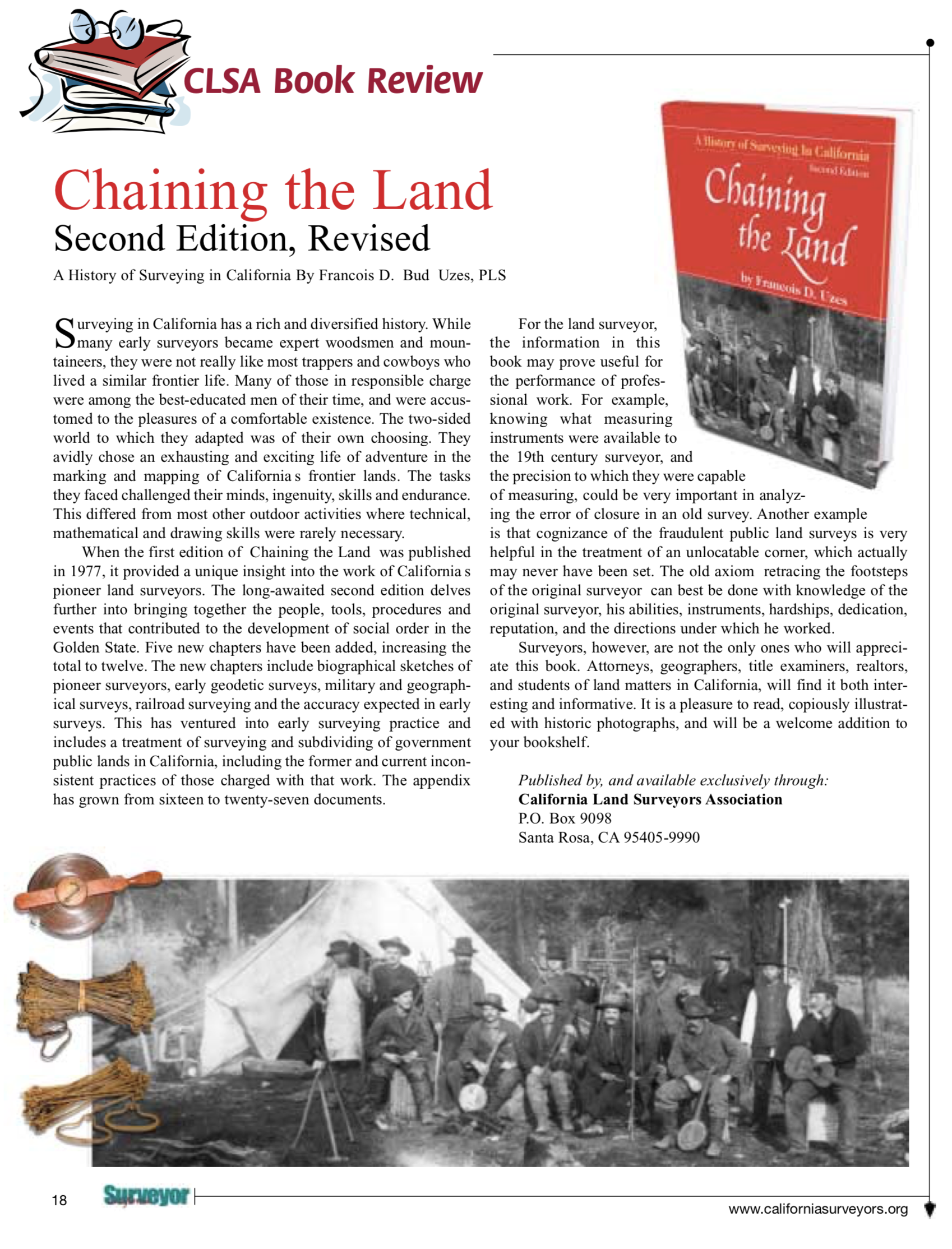
Bud published the Second Edition of Chaining the Land in 2006. He actually sent the final draft to the printer right before he passed away (unexpectedly). By this time Bud and I were 11 years into The Compleat Surveyor business, so I was a bit more involved in this book than the others before it. Bud added a lot of material - the book grew to 495 pages.
Here is a 2006 California Land Surveyors Book Review that contains more details about the Second Edition.
The Bud Uzes Collection
Bud collected old surveying instruments and books for roughly 40 years, and built a really nice collection of both instruments and books. I wish I had better pictures of his collection, but my dad was always a generation behind on digital cameras -I gave him my hand me downs.
Solar Instruments
Burt's Improved Solar Compass, Wm. J. Young, maker, Philadelphia, PA, c. 1844.
This Circa 1844 Young Solar Compass has no serial number. The latitude and declination arcs have no slow-motion adjustment screws (tangent screws) as was the design on the earlier solar instruments. According to Robert Miller, there are now eight known solar compasses made by Young that are without serial numbers, i.e., made during the period 1840–1852.
This instrument is 14" long and has 7" high sight vanes. One arm is inscribed "Wm. J. Young, Maker, Philadelphia." The same arm also has the stamped mark of “J Roach, SF.” The opposite arm is inscribed "Burt’s Patent." The instrument comes with a ball-joint type of mount that is 7” long and has four clamp screws in the base socket. The magnetic needle is 3½” long. The J. Roach stamping is a later addition to the instrument.
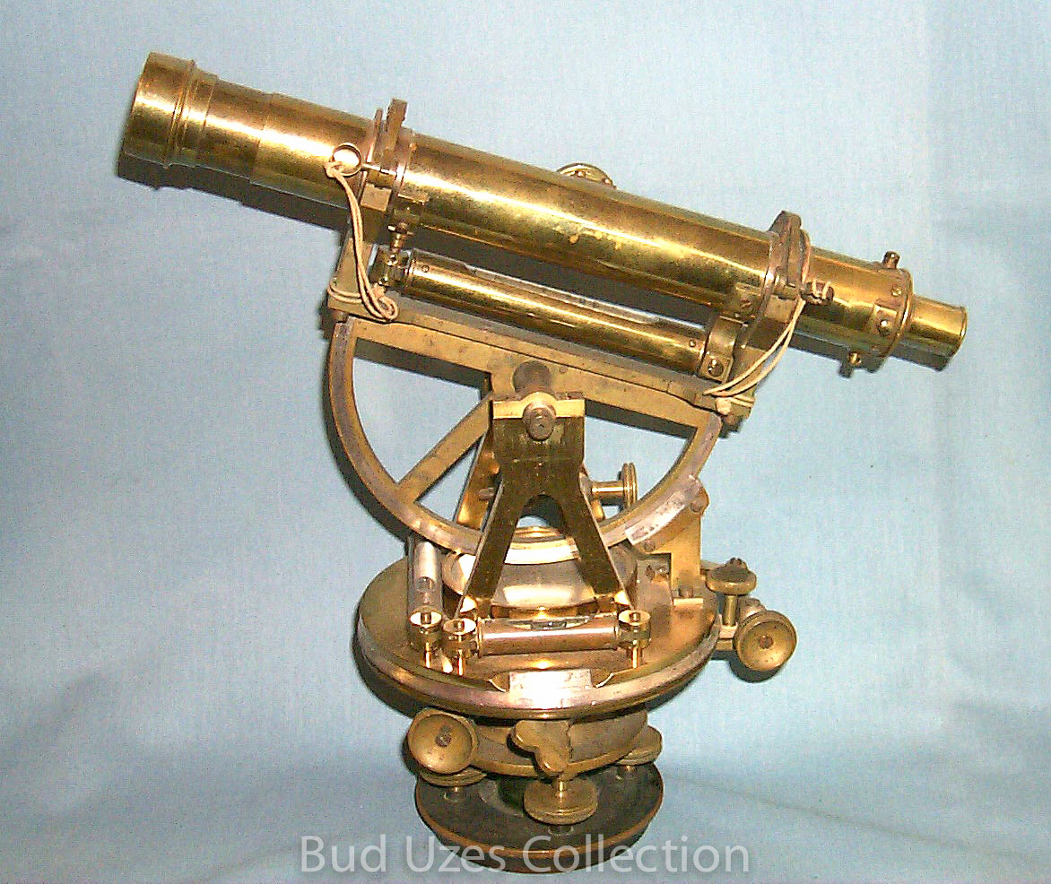
Burt's Improved Solar Compass, Wm. J. Young, maker, Philadelphia, PA, c. 1852.
This Circa 1852 Young Solar Compass is 14.2" long and has 7.1" high sight vanes. It also has a telescopic sight to use instead of the vanes. The 7.3" telescope has a full vertical circle and vernier with no set clamp. The compass is 12 1/4" tall with the telescopic sight and 13 1/3" tall with the vanes. There is a counterweight for attaching to the opposite arm when the telescopic sight is used. The latitude and declination arcs have slow-motion adjustment screws which, according to Robert Miller, are later modifications. The eyepiece arm is inscribed "Wm. J. Young, Maker, Philadelphia." The opposite arm is inscribed "Burts Patent." The instrument would fit onto a tripod with male threads of approximately 3 7/8” x 14.
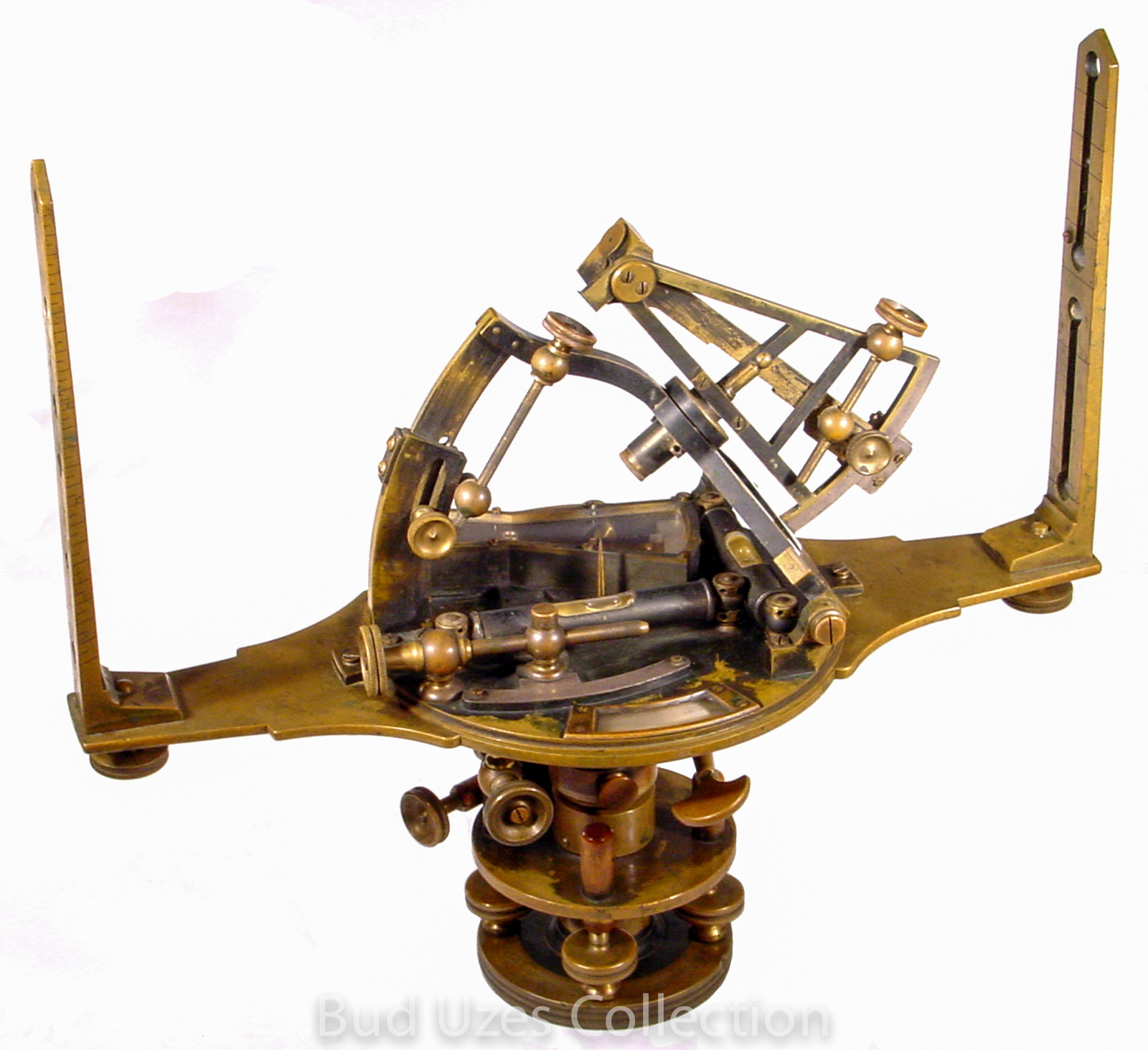
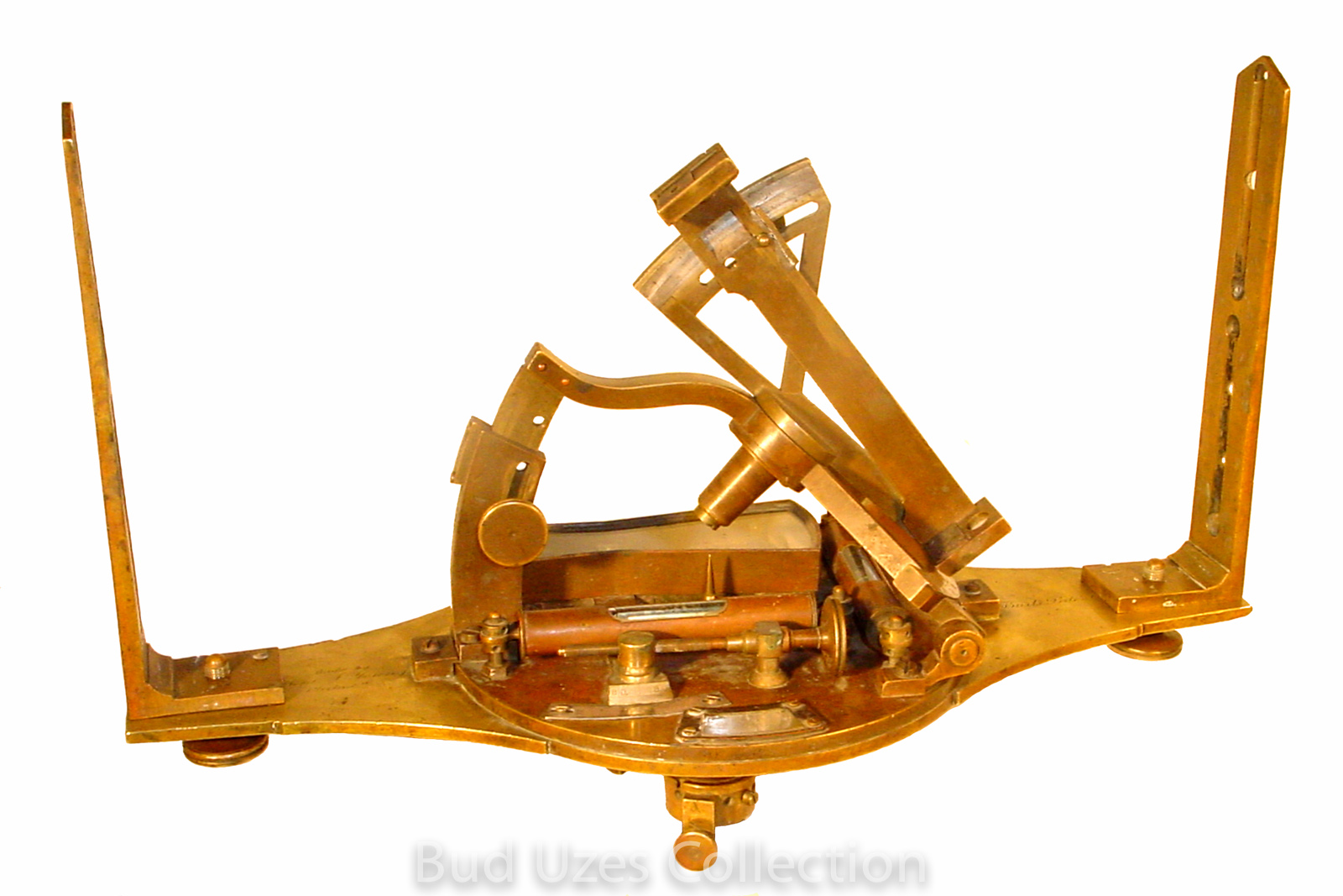
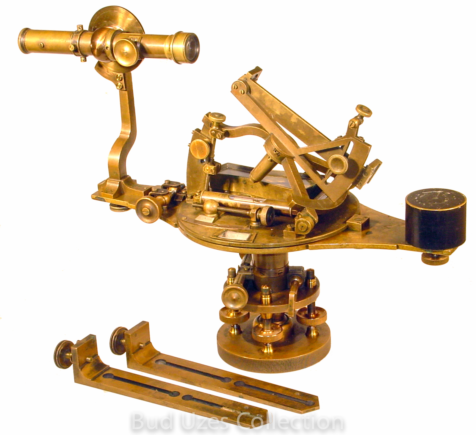
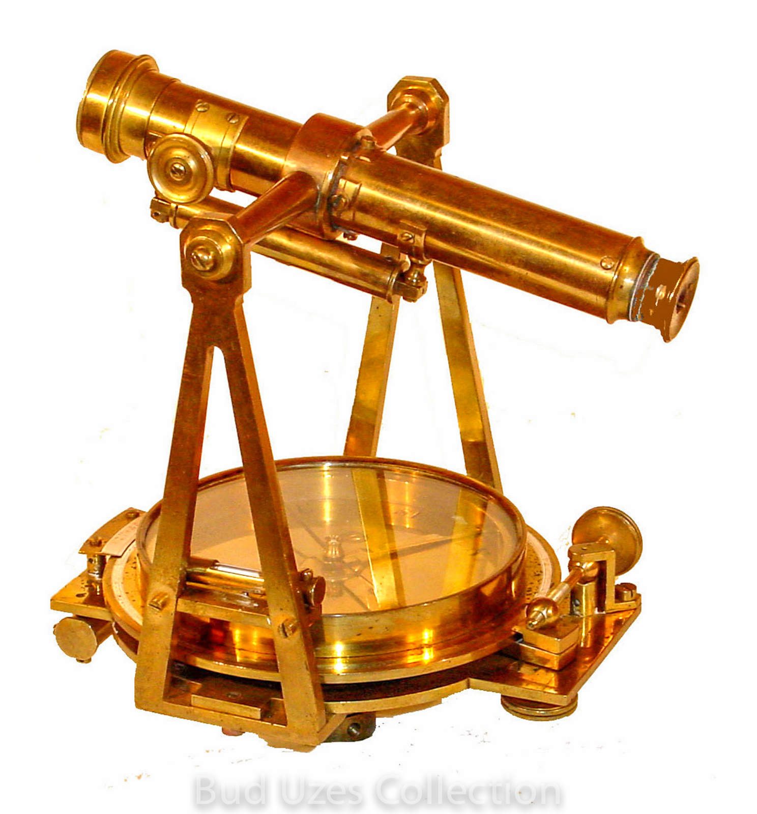
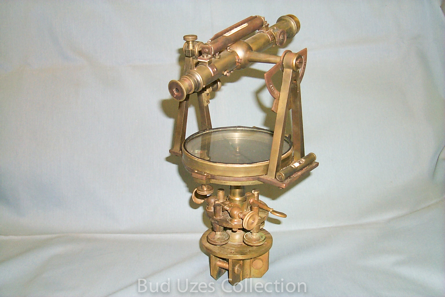
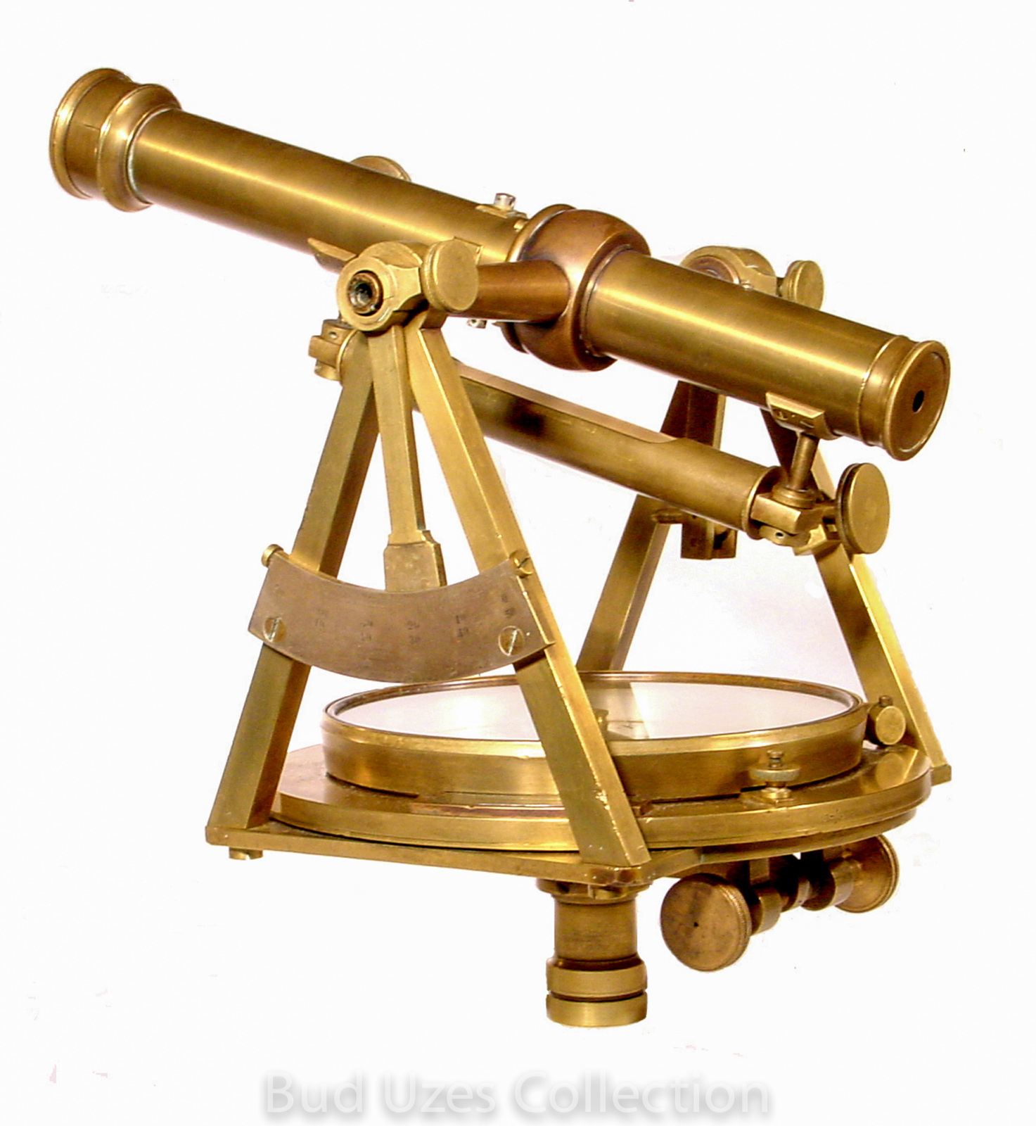
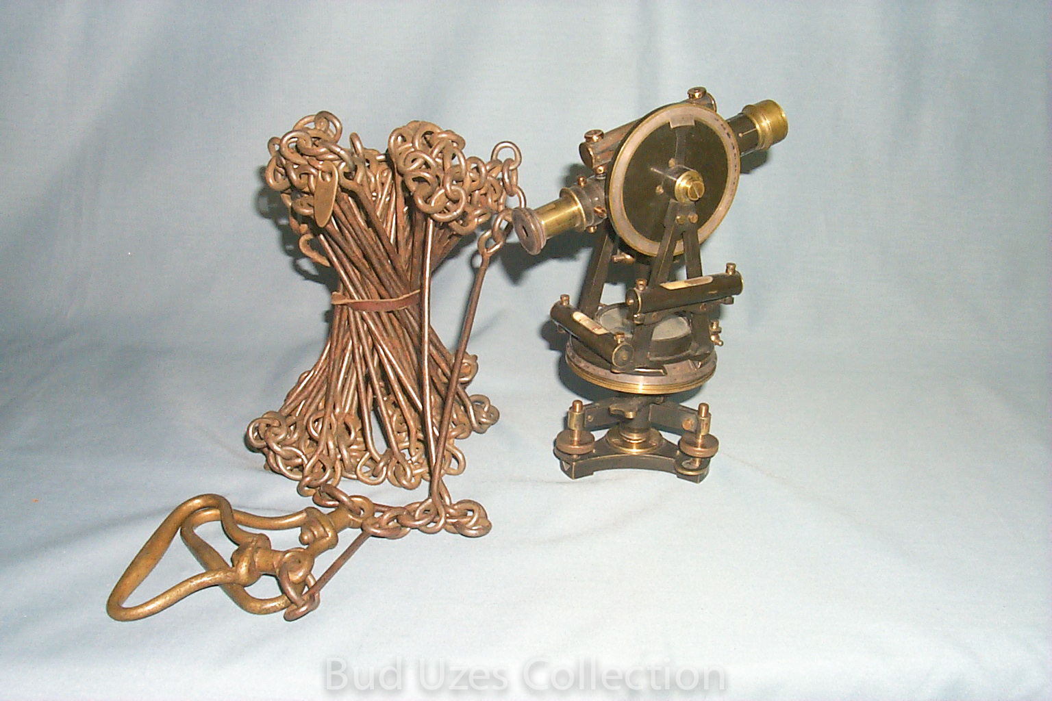
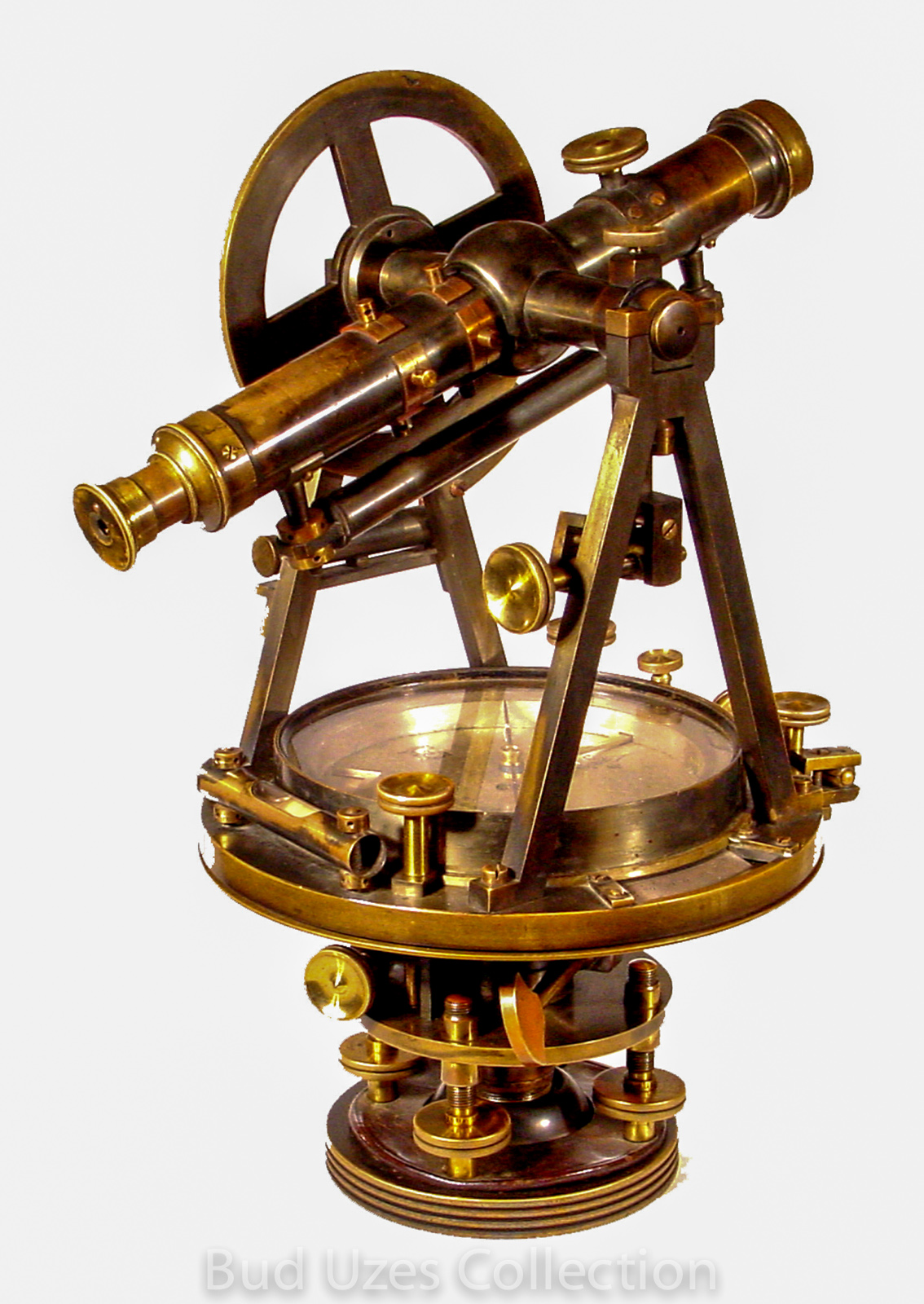
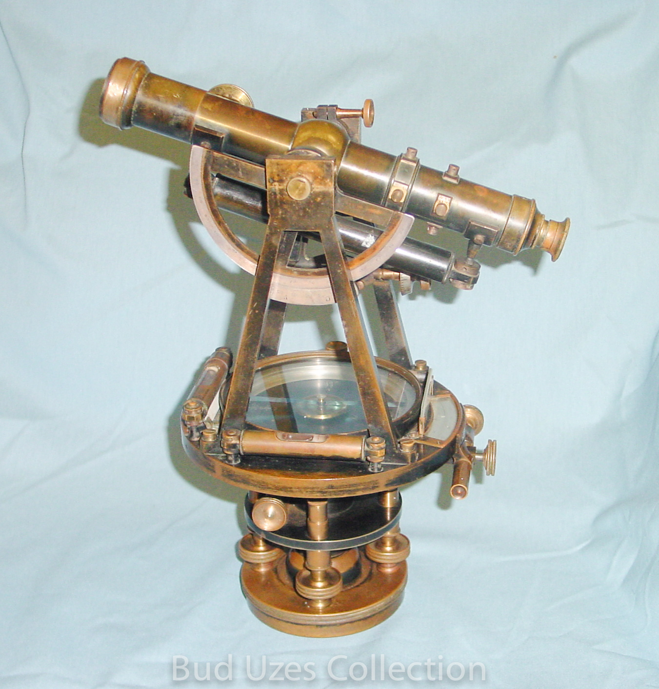
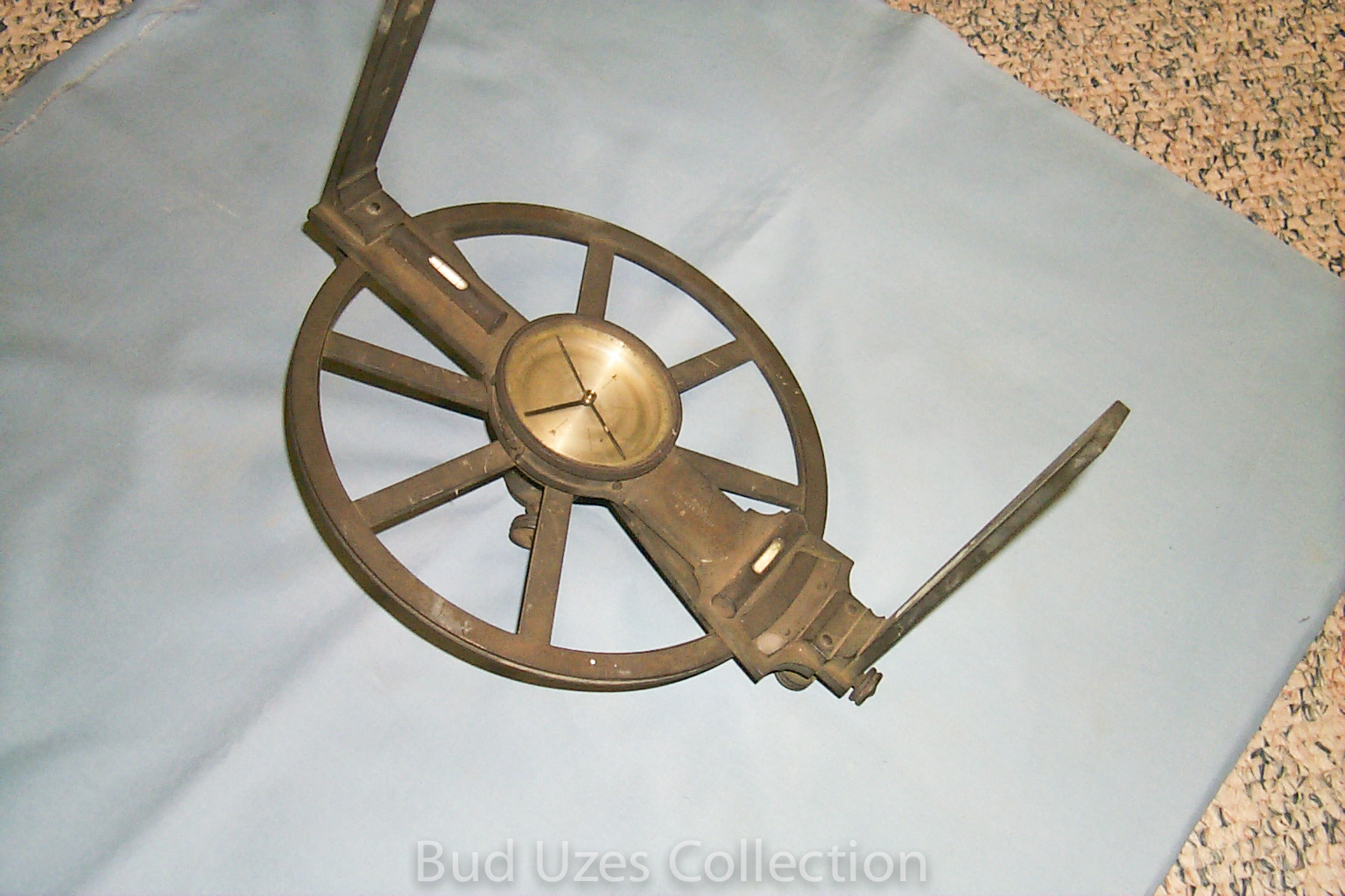
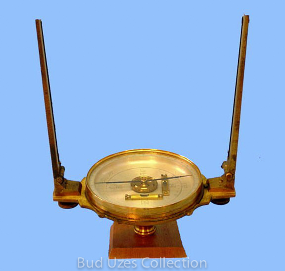
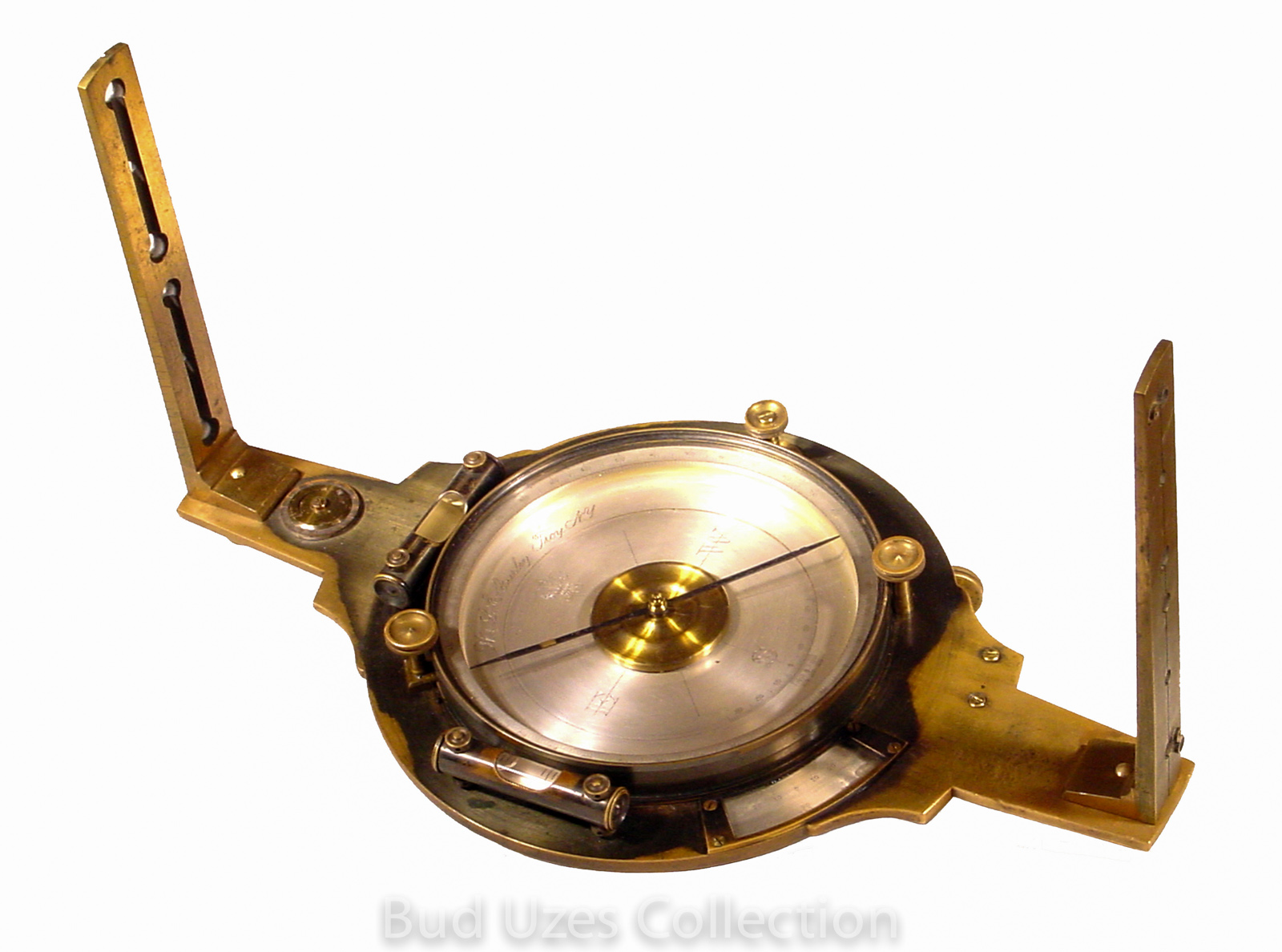
Burt's Improved Solar Compass w/Clamp-on Telescope, W. & L.E. Gurley Co., maker, Troy, NY, c. 1894.
This Circa 1894 Gurley Solar Compass was previously owned by John C. Bliss in Nevada, and supposedly was used by him near Glacier National Park. The Bliss family was prominent in the Carson City - Lake Tahoe area, noting Bliss State Park at the lake.
The instrument is 18" wide with the telescope horizontal, and 13¼" high. The telescope is 8 3/4" long and has a patent date of July 9, 1878. The sighting vanes are each 7 3/4" high. There is a box compass with a 3½" needle. The horizontal circle is 5½" in diameter, and has a single one-minute vernier. This solar compass is pictured on the back cover of the 1980 illustrated price guide, and with me on page 11 of Chaining the Land.
360 Degree View (from 1999) mp4
360 Degree View (from 1999) mv4
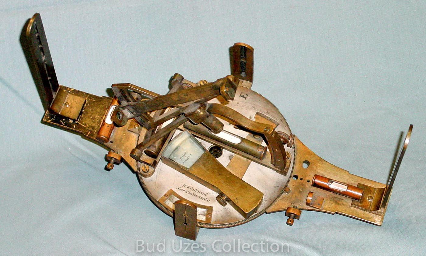
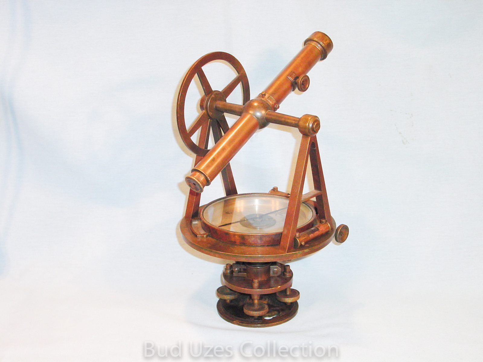
Burt's Improved Solar Compass, Rasselas Whitcomb, maker, New Richmond, OH, c. 1840s.
Bud owned this Circa 1840s Whitcomb solar compass for a short period of time before selling it to his close friend and colleague, Roy Minnick. The solar compass has several holes drilled into the sighting arm. It seems there was once a telescopic attachment for this and some of the brass brackets are still present in the case but there is no telescope. It comes with a wood case plus a modified Gurley (?) tripod that has the typical compass stem top with no leveling base.
Light Mountain Transit w/Burt Solar Attachment, W. & L.E. Gurley Co., maker, Troy, NY, c. 1899.
This instrument has a 5 3/4" horizontal circle and a 4" needle. It has a partial vertical circle. Inside the instrument is scratched "Wood 4-19-07 Wenzel, Seattle 5/6/1908." The transit with attachment is 13 1/2" tall.
Mountain & Mining Solar Transit, A. Lietz Co., San Francisco, SN 1221, c. 1900
This is a Lietz No. 12 aluminum transit. The top of the telescope is fitted for a Saegmuller-type solar attachment and counterweight that come in separate case. The transit has a 4" horizontal circle, a 4" vertical circle, and a 2 1/2" compass needle. There is a gradienter device on the vertical tangent screw. The transit is serial number 1221.
Mountain Solar Transit, Young & Sons, maker, Philadelphia, PA, Serial No. 8375, c. 1909.
This Circa 1909 Young & Sons Solar Transit is Y&S Catalog No. 10. It is made of aluminum and brass construction and is fitted with a Smith Telescopic Solar Attachment. It is 13'" high, and has a 4½" horizontal circle, a 4" vertical circle, a 3.3" needle, and a 10" main telescope. The telescope on the Smith solar unit is 7" long, and is inscribed "Pat Sep 16, 1902." There is a counterweight on the standard opposite the side with the solar unit. The leveling base is from a 1908 patent. It is complete with case and tripod.
Wet Mining Transit, C.L. Berger & Sons, maker, Boston, MA, Serial No. 7814, Catalog No. 4C, c. 1915.
This 12" high instrument has a 4" horizontal circle, a 4" replacement vertical circle, a 2½" magnetic needle, a 7½" main telescope, and a 4½” auxiliary telescope. This instrument was ordered from the Berger factory on Jan. 20, 1909 by the Salt Lake Blue Print Co., Salt Lake City, UT. It is a Berger 4C Mining Transit.
Solar Transit, Buff & Buff Mfg. Co. Boston, MA, Serial No. 14240, c. 1920.
This is a USGLO Model-A Solar Transit, Model of 1914 and was purchased new by the USGLO in 1920. The telescopic solar attachment is a modification of the Smith design. The transit is 11" tall and has a 2-inch magnetic needle, a 4 1/2-inch horizontal circle reading to one minute of arc, a 4-inch vertical circle also reading to one minute of arc, a 9-inch main telescope with level underneath, and a 6-inch side-mounted solar telescope.
Transits
Plain Theodolite w/Geared Vertical Limb, George Adams, maker, London, c. 1790.
George Adams, Jr. (1750-1795) was a leading maker of mathematical instruments. He was instrument-maker to George III in succession to the elder George Adams (1704-1773), and optician to the Prince of Wales. He wrote numerous books of a scientific nature.
The instrument has a 7¼" horizontal circle, a 7¼" vertical arc, and a 4" needle. The vertical circle is divided from -41° to +105°. The telescope is 13.2" long. It is inscribed "G. Adams, London." The upper horizontal limb under the objective end of the telescope has divisions, noted by the inscribing "Tang. to 100 of Radius." The instrument is depicted on Plate 16 of George Adams' Geometrical and Graphical Essays, 2nd ed., 1797. It is complete with case and tripod.

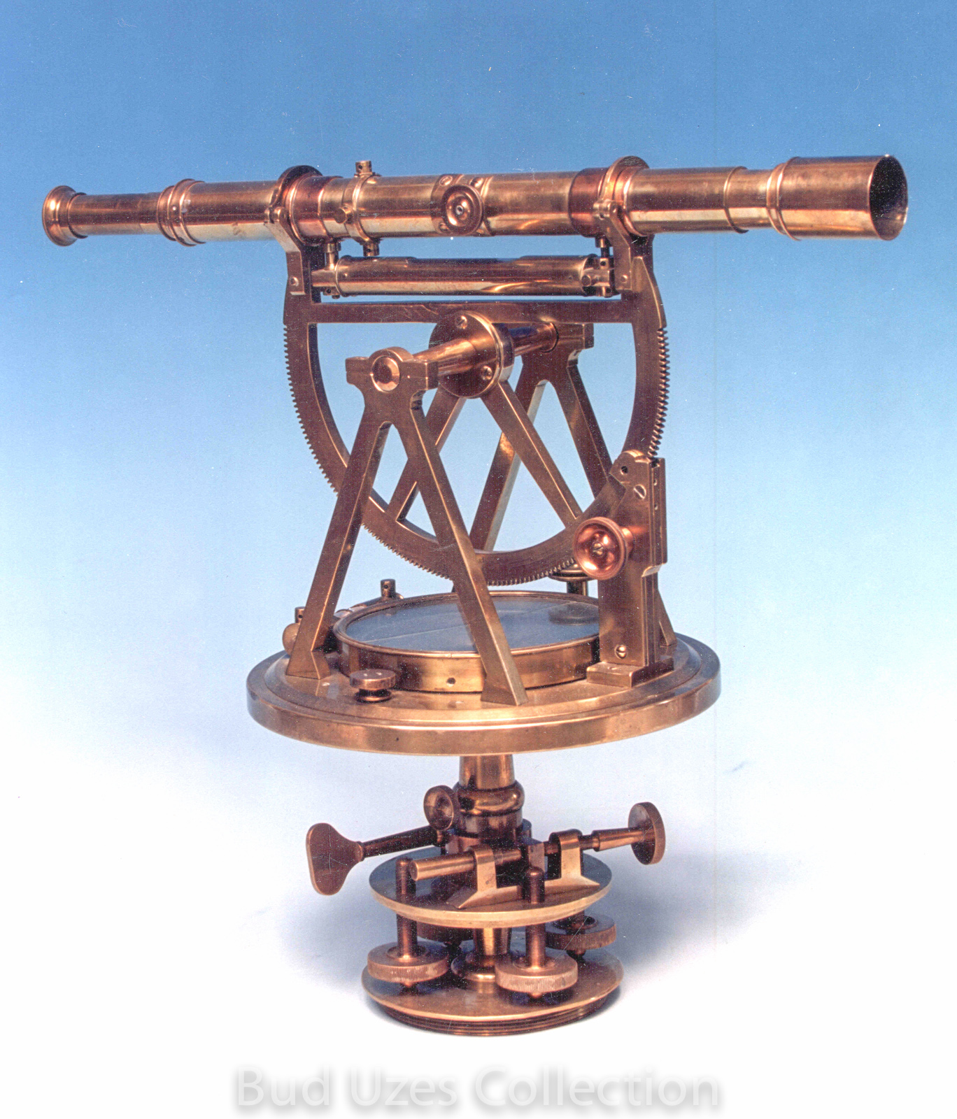
Cradle Theodolite w/Geared Vertical Limb, M. Berge, maker, London, c. 1818.
This is the type of telescopic angle-measuring instrument used prior to being replaced by the transit. It is 9 1/2" high with a 10-inch erecting-image telescope. Matthew Berge was a noted English maker of quality scientific instruments. He reportedly worked for and was successor to the firm of Jesse Ramsden when Ramsden died in 1800. The instrument has a 5" horizontal circle and a 5" vertical geared arc, both reading to one miinute. There is a 2 1/2" long telescope level and two plate levels. There is no close-focus mechanism as typical of later instruments.
Surveyor's Transit, Richard Patten & Son, Maryland, c. 1850.
This is a unique design of surveyor's transit and is described in Robert Miller's article in Rittenhouse, Vol. 7, Issue 28, August 1993, titled "The First Surveyor's Transits, 1852-1862." This style has the standards attached to the lower horizontal plate instead of the upper. It was intended for retracing land boundaries rather than for engineering purposes. The transit has a telescope 8 1/2" long, a 4 1/2" long compass needle, and a horizontal circle 6 inches in diameter reading by vernier to one minute of angle. There is one spirit level located just below the horizontal plate, another on one of the standards, and a third affixed underneath the telescope. There is no vertical circle.
The transit has no leveling base but instead sits on a spindle affixed to a tripod. The spindle has its own leveling mechanism with 4 screws.
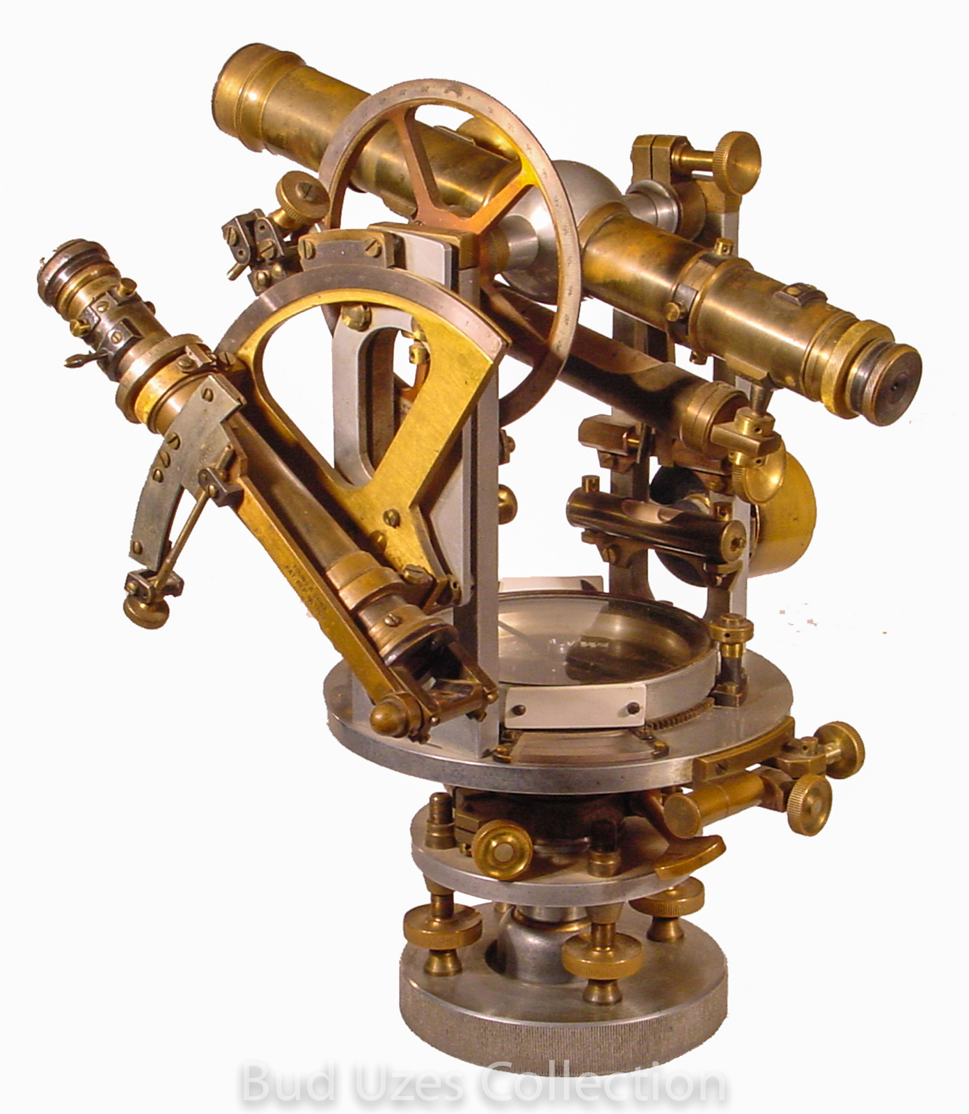
Surveyor's Transit, James Reed & Co., Pittsburg, PA, Serial No. 408, c. 1857.
James Reed (1792-1878) began trading as James Reed & Co. in 1850, and in 1852 advertised as "Manufacturers of theodolites, surveyors compasses, leveling & grading instruments, &c. ." This design of surveyor's transit is unusual in that the 4” diameter horizontal circle is smaller than the 5” compass circle and is located inside the compass box. The horizontal circle is divided in half degrees of arc and read by vernier to one minute. There is a 140 degree vertical arc divided to one degree and read by vernier to 5 minutes.There are two 1.1” long spirit levels mounted on the horizontal plate, and a 4½” level affixed above the telescope. The instrument is rotated horizontally by turning a knob that by means of a gear mechanism turns the geared exterior of the upper mechanism.
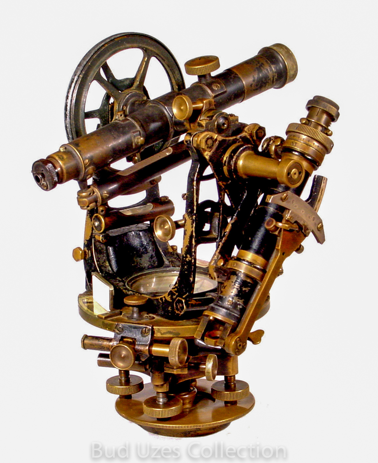
Surveyor's Transit, William Schmolz, San Francisco, c. 1858.
This is a unique design of surveyor's transit known as "Pre-1862 Surveyor's Transits" and is described in Robert Miller's article in Rittenhouse, Vol. 7, Issue 28, August 1993, titled "The First Surveyor's Transits, 1852-1862." This style has the standards attached to the lower horizontal plate instead of the upper. These special instruments were constructed so that the compass card and needle ring remain stationary when the transit is rotated in azimuth with the lower plate clamped. The transit has a telescope 10 3/4" long, a 6 1/4" telescope level, and a 4 3/4" long compass needle. The horizontal circle is 6 inches in diameter reading by vernier to one minute of angle. There is one spirit level located just below the horizontal plate, another on one of the standards, and a third affixed underneath the telescope. There is a vertical arc but no vertical circle. The transit has no leveling base but instead is the type that sits on a spindle affixed to a tripod. The spindle has its own leveling mechanism with 4 screws. The horizontal limb reads to one minute on the vernier, and the vertical arc reads to three minutes with an angle range of 50 degrees each way.
Single Vernier Surveyor's Transit, Edmund Draper, maker, Philadelphia, PA, Serial No. 174, c. 1860.
This instrument is 12 1/2" tall and has a 6" horizontal circle, a 5" vertical circle, a 4.6" needle, and a 10.6" long telescope. There is no clamp mechanism to the telescope. The compass box is inscribed "Edmund Draper, Philadelphia, 174." The dating is according to information provided by Robert Miller who has a number of Draper instruments, some with serial numbers and others without.
Single Vernier Surveyor's Transit, W. & L.E. Gurley Co., maker, Troy, NY, c. 1870
.
This 14" tall instrument has undocumented provenance to 19th century surveyors Hatch & Eaton in Nevada. It was reportedly used by them in 1871 on public land surveys and for the early layout of the NCO Railroad.
The compass dial is inscribed "W. & L.E. Gurley, Troy, N.Y., Chas. G. Ewing, Agent, San Francisco, Cal." It has a 6.6" horizontal circle, a 3.6" vertical circle, a 5" magnetic needle, and an 11" telescope. The leveling base is detachable from the upper portion of the instrument. Charles Ewing was the S.F. agent for Gurley during about 1869-1882.
This instrument is pictured on page 31 in Chaining the Land.
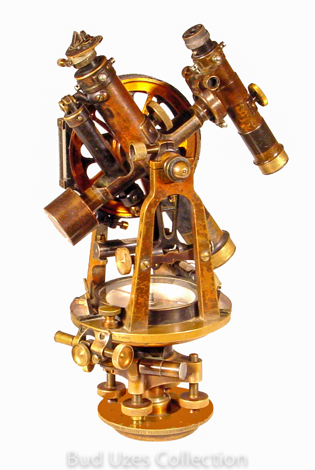
30" Surveyor's Transit, John Roach, maker, San Francisco, CA, c. 1872.
This is a fine example of this noted pioneer California maker. It has a 7" horizontal circle to 30 seconds, and a 5" full vertical circle to 1 minute, and a 4 3/4" compass needle. The transit is 13 1/2" high and has a telescope 10 1/2" long. The compass dial has fancy original swirl polishing. The Smithsonian NMAH website states that Roach moved to San Francisco in 1855, and was soon the leading instrument dealer on the West Coast.
3" Traveller's Transit Theodolite, L. Casella, maker, London, Serial No. 3712, c. 1875.
This tiny instrument comes with several accessories including a separate high-power eyepiece. It is brass construction finished in black and brass finish. It has a wood case plus a cloth case for the wood. It has a 2.75" horizontal circle, a 2.5" vertical circle, a 1.5" needle, and a 6" telescope with the low-power eyepiece. The compass box is inscribed "L. Casella, Maker to the Admiralty & Ordnance, London, 3712." The graduations to the horizontal circle are external. The tangent screws are not spring-opposed.
30" Surveyor's Transit, John Roach, maker, San Francisco, CA, S/N 761, c. 1885.
This is a fine example of this noted pioneer California maker. It has a 6" horizontal circle to 30 seconds, a 5" vertical arc to 20 seconds, and a 4” compass needle. The transit stands 12 3/8" high and has a telescope 11" long. There is also a gradienter plus stadia hairs in the telescope. The instrument is complete with original tripod and case. It is signed John Roach, Maker, San Francisco, 761. The tripod is imprinted with the serial number 761 as is the wooden tripod cap. There is also a 15 oz. plumb bob signed J. Roach, S.F. CAL having the number 25 is imprinted on the neck.
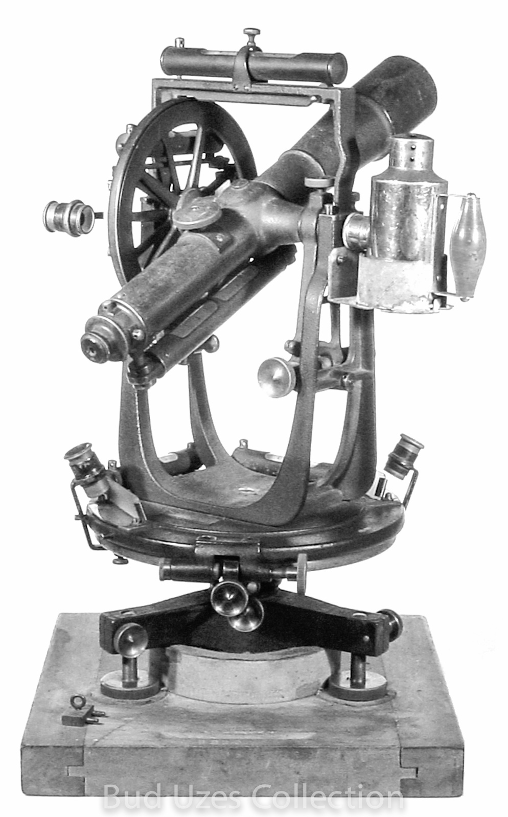
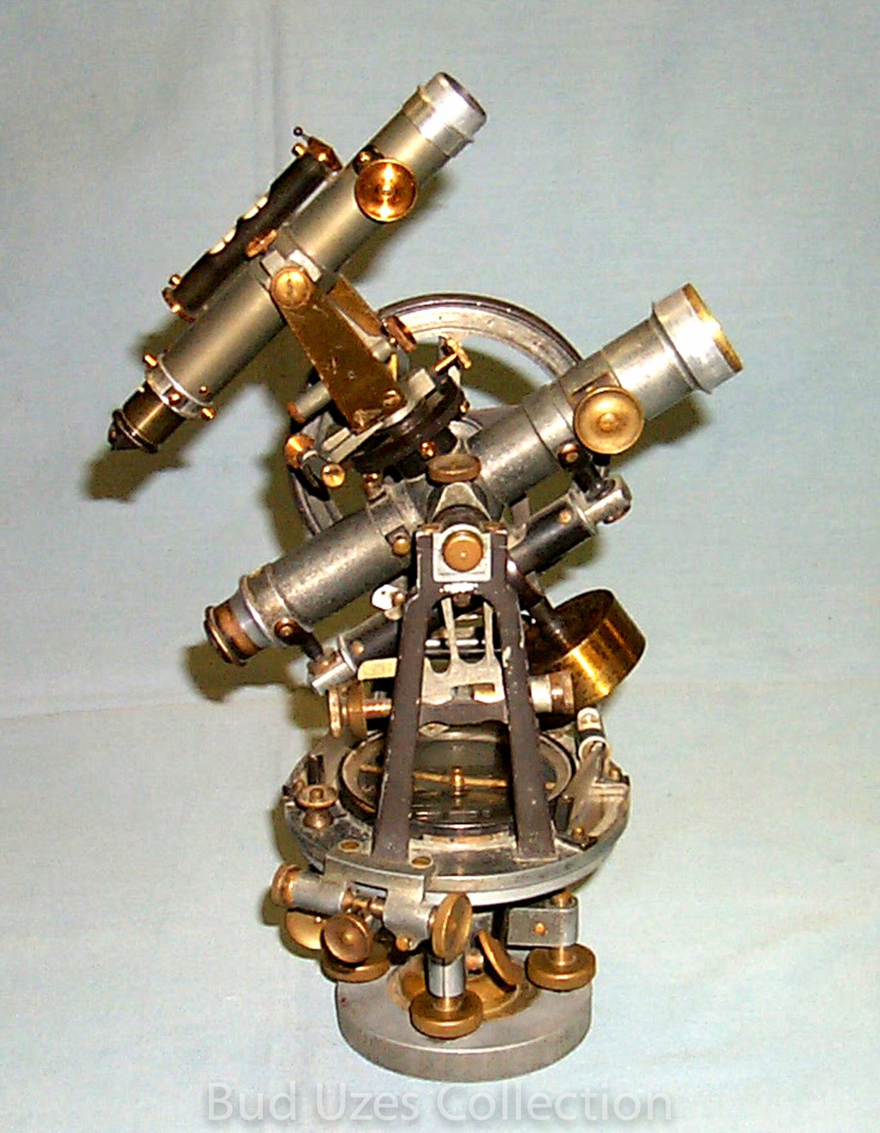
Boundary Precision Theodolite, A. Lietz Co., San Francisco, Serial No. 8990, c. 1922.
This large surveying instrument is Lietz's Model No. 5 U.S. The circle diameters are 7 inches horizontal and 5 inches vertical. Both circles have two verniers. They are read to 10 seconds and 30 seconds of arc, respectively, using four individual built-in microscopes. The telescope is 12 inches long with inverting image. A striding level mounts across the standards to assist in final leveling, and extra eyepieces and an additional reticle are included inside the telescope case. An oil-burning lamp illuminates the telescope cross hairs when working under low light conditions. The lamp mounts near the top of the left standard and shines light through the hollow axle into the telescope.
Cradle-type Plain Theodolite, J.M. Hyde, Bristol, England, c. 1845.
This is the classic English plain theodolite used in America for angular measurement until the mid 19th century. It was then being replaced by the surveyor's transit although the popular Davies Surveying text continued to include the theodolite until the 1883 edition. This 11 1/4" tall instrument has a 12-inch telescope set in wye supports with a 4 1/2-inch level mounted underneath. There is also an exterior 5 1/2-inch horizontal circle reading by vernier to one minute of arc, a 6-inch diameter vertical half circle reading to one minute, and a 2 1/4-inch compass needle.
Compasses
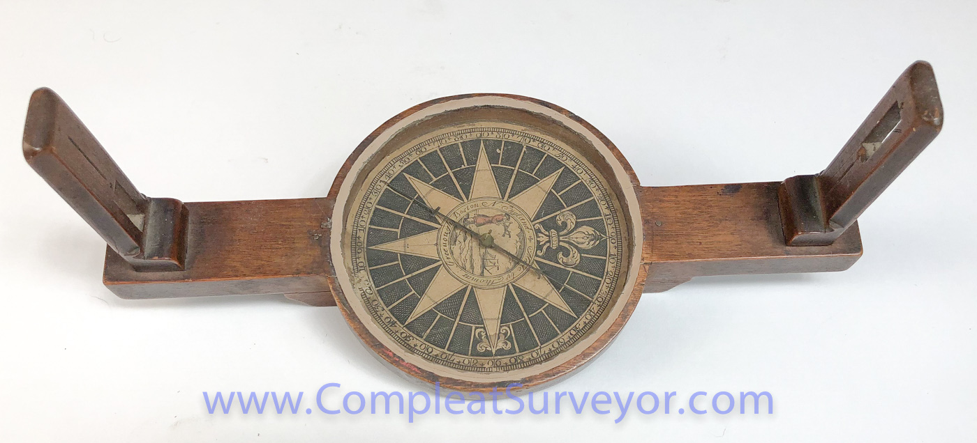
Surveyor's Plain Compass, Thomas Greenough, maker, Boston, New England, c. 1760.
This compass is possibly made of cherry wood. It is 12.2" long, has 4" high sights and a 4.2" long needle. The paper compass card shows a man in a red coat looking out to sea with a quadrant instrument, and a sailing vessel on the horizon. The card has printed divisions of 0° to 90° in each of the four quadrants. There is some damage to the divisions in the vicinity of S 15° W, considering that W is on the E side of the card as customary. The paper compass card was possibly printed by Paul Revere. With the compass is a contemporary hand-carved 54" hickory tripod.
The inscription on the compass card reads "Made by Thomas Greenough, Boston, New England." Compasses by Thomas Greenough are pictured and described in Silvio Bedini's Early American Scientific Instruments and Their Makers, 1964, at pps. 85-93.
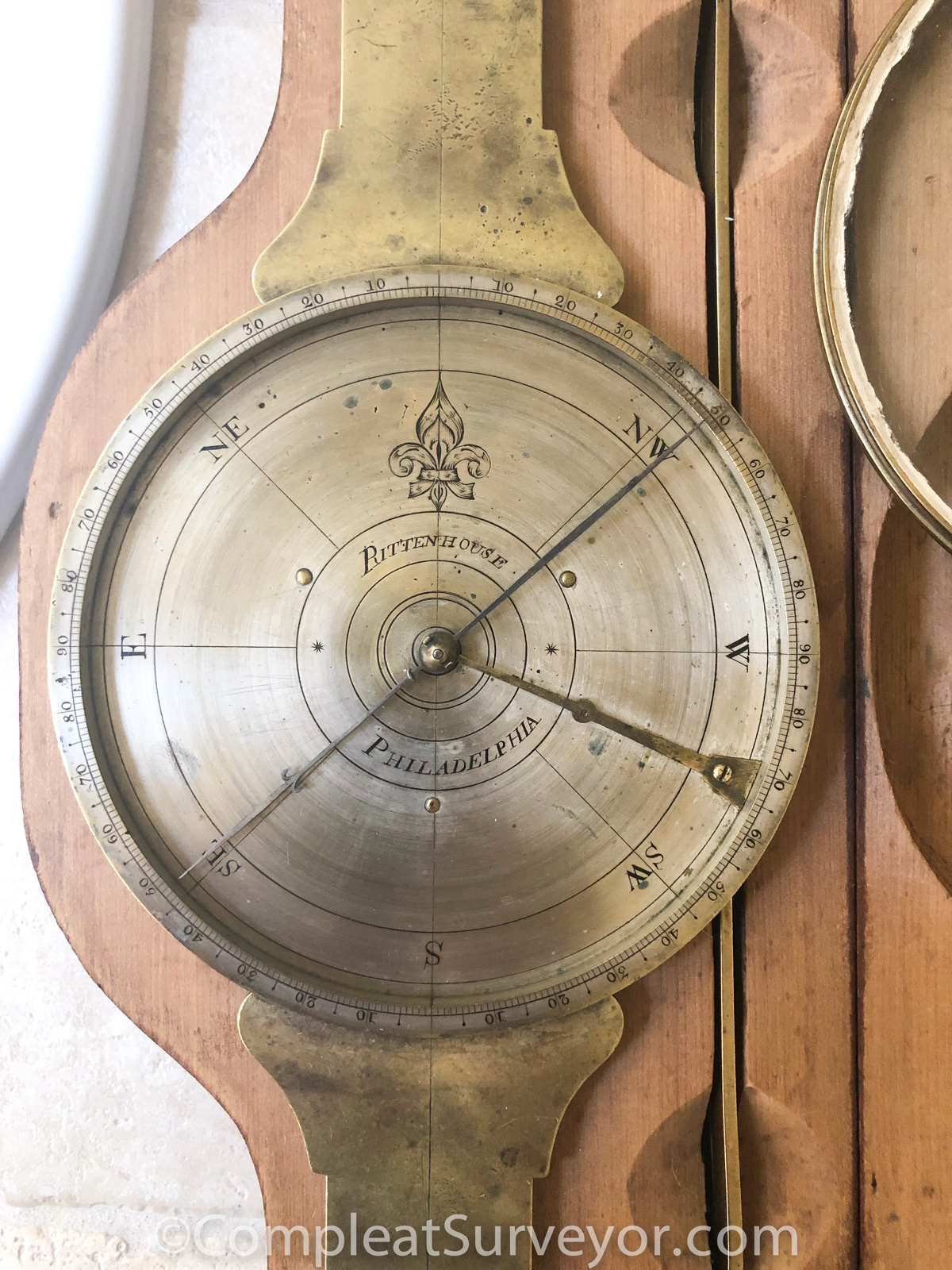
Surveyor's Plain Compass, [David?] Rittenhouse, maker, Philadelphia, PA, c. 1771.
Probably made by David Rittenhouse rather than by his brother, Benjamin (see RITTENHOUSE, 5:1, Nov. 1990, pps. 1-16, w/picture pp. 8). This compass has an automatic needle lifter, and is believed to be the first instrument with such a device. David Rittenhouse was a leading American scientist of the revolutionary war period. He was very inventive and not inclined to decorate all of the compasses he made. All known compasses by Benjamin are highly decorated (see Bedini: THINKERS AND TINKERS, pp. 211).
This instrument is inscribed "RITTENHOUSE, PHILADELPHIA." It has a simple compass dial absent of decoration.
The present compass is 14.2" long, has removable sights 6.3" high, a 5.5" needle, brass cover to compass box, and a contoured wood case.
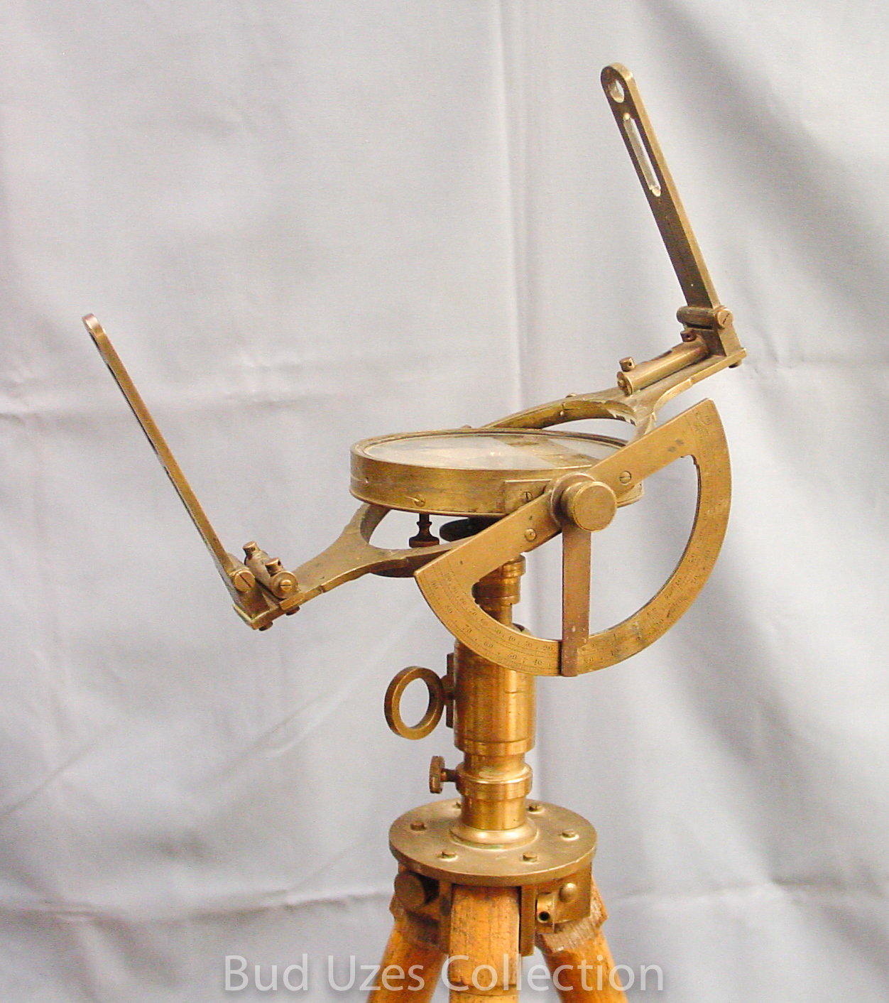
Simple Theodolite w/Circumferentor, T. Blunt, Cornhill, London, c. 1790’s.
The instrument has a 5/16” thick outer graduated circular ring of 10 inches diameter. Mounting onto this ring are two 5.3-inch sight vanes that slide into dovetail slots located on the underneath side. Moving independently of the fixed ring is a concentric circumferentor with sighting arms. The overall length of the rotating circumferentor is 9.4”, and the end of the north arm is divided with a 3-minute vernier that is used for reading horizontal angles in conjunction with the divided outer ring. All divisions on the instrument are cut by hand. The circumferentor has separate 4.4-inch sight vanes that are attached by sliding into dovetail slots located on top of the arm near the outer ends. The purpose of having two sets of sight vanes is to enables the surveyor to measure angles independent of the magnetic needle, hence its being called a theodolite. Inside the elaborately engraved 5-inch diameter compass box are two 2-inch spirit levels at right angles to one another. There is no needle arrestor. A conical staff mount is below the compass.
Surveyor's Plain Compass, [Samuel] Browning, maker, Boston, c. 1816.
This plain surveyor's compass has brass sighting vanes and compass ring on a mahogany base. The overall length is 15", the compass box is 6 3/4" diameter, the needle 5" long, and the sights are 4 3/4" high. The paper compass card at the north end is imprinted Browning, Boston and at the center is marked Browning Maker from London. An identical instrument is in the Henry Ford Museum in Dearborn, Michigan and described in Charles Smart's book.
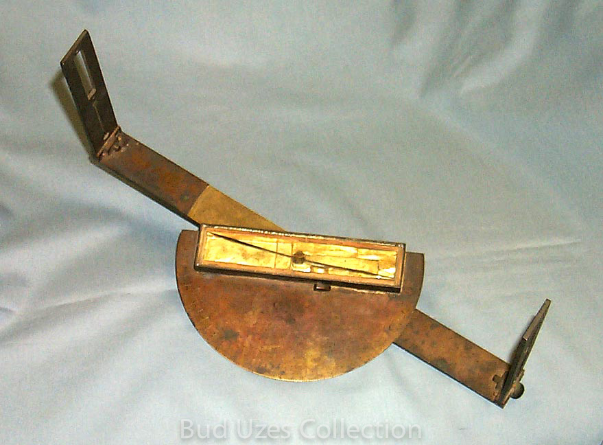
Graphometer, Unsigned, c. 1760
This instrument was found in Washington, DC and is believed to be of American manufacture. The sighting bar is 13¾” long and the sights are 6 1/6” high. There is a trough compass with needle of 5 ½” length. The needle has the letter N inscribed in the north end. The bottom of the trough compass is lined with a gold-colored foil or thin sheet metal. The diameter of the hand-divided arc is 7”. The construction is unique in that the hammered-brass sighting bar is formed of brass plate with layers bonded together by brass pins (or dowels). The trough compass is similarly formed with the use of pins. The divisions on the arc are not numbered with engraved figures, but appear to have been originally distinguished with painted numbers.
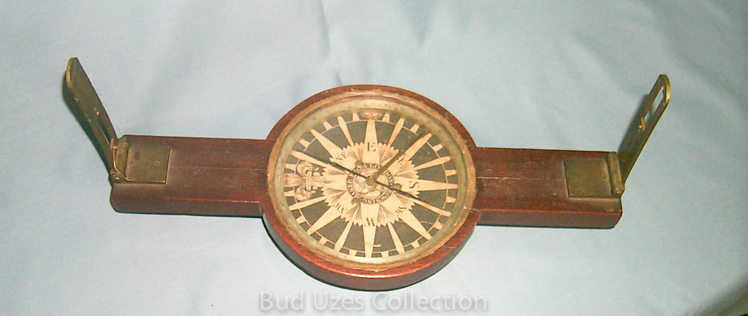
Surveyors Plain Compass, Alexander Megarey, New York, c. 1833.
This compass is 13.8" long, has sights 6.3" high, and a 5" magnetic needle. It is complete with wood case including an original label and the original tripod with a ball-joint adapter. The compass dial is signed in script Alex Megarey, and in block letters N. York. Megarey is listed in Smart as being in business from 1827 to 1850, the last address being at 190 Water Street. The label in the wood case shows 238 Water Street where the Webster database lists him during the years 1831 – 1835.
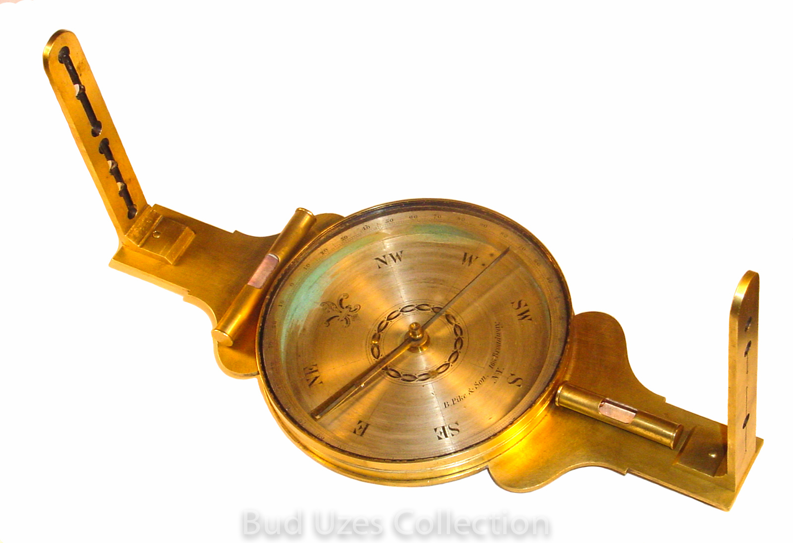
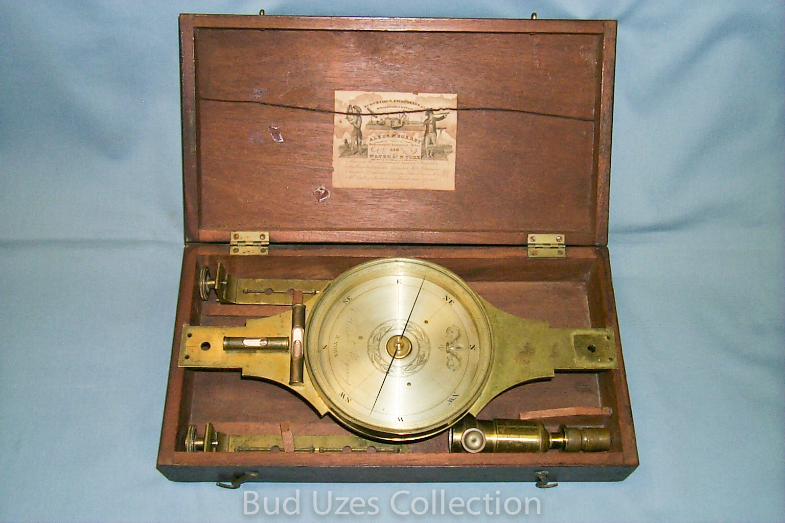
Surveyors Plain Compass, B. Pike & Son, New York, c. 1845.
This compass is 15" long, has sights 6½" high, and a 5¾" magnetic needle. It is complete with original wood case and a ball-joint staff adapter. The outside top of the wood case is imprinted with two names, older being Capt. Ord USA and the other B.F. Garloff. The inside of the case cover has the names B.F. Garloff, J.G. Colyar, and Alona & Senter Ord. The Ord name is famous in American history and early California surveying as in 1849 he made the first survey of the City of Los Angeles. The compass dial is signed in script B. Pike & Son, 166 Broadway, New York. The B. Pike & Son firm is listed in Smart as being in business from 1831 to 1841, and then again from 1843 to 1850. Two addresses were used, the later being 166 Broadway. There are two level vials both with fluid.
Simple Theodolite w/Circumferentor, Spencer & Compy., London, c. 1817.
The instrument has an outer graduated circular ring of 10 inches diameter. There is a vernier reading to 3 minutes of arc on one of the sighting arms. The compass box is 5 inches diameter and the magnetic needle is 4 inches long. The sights extend approximately 5 1/2 inches above the divided circle.
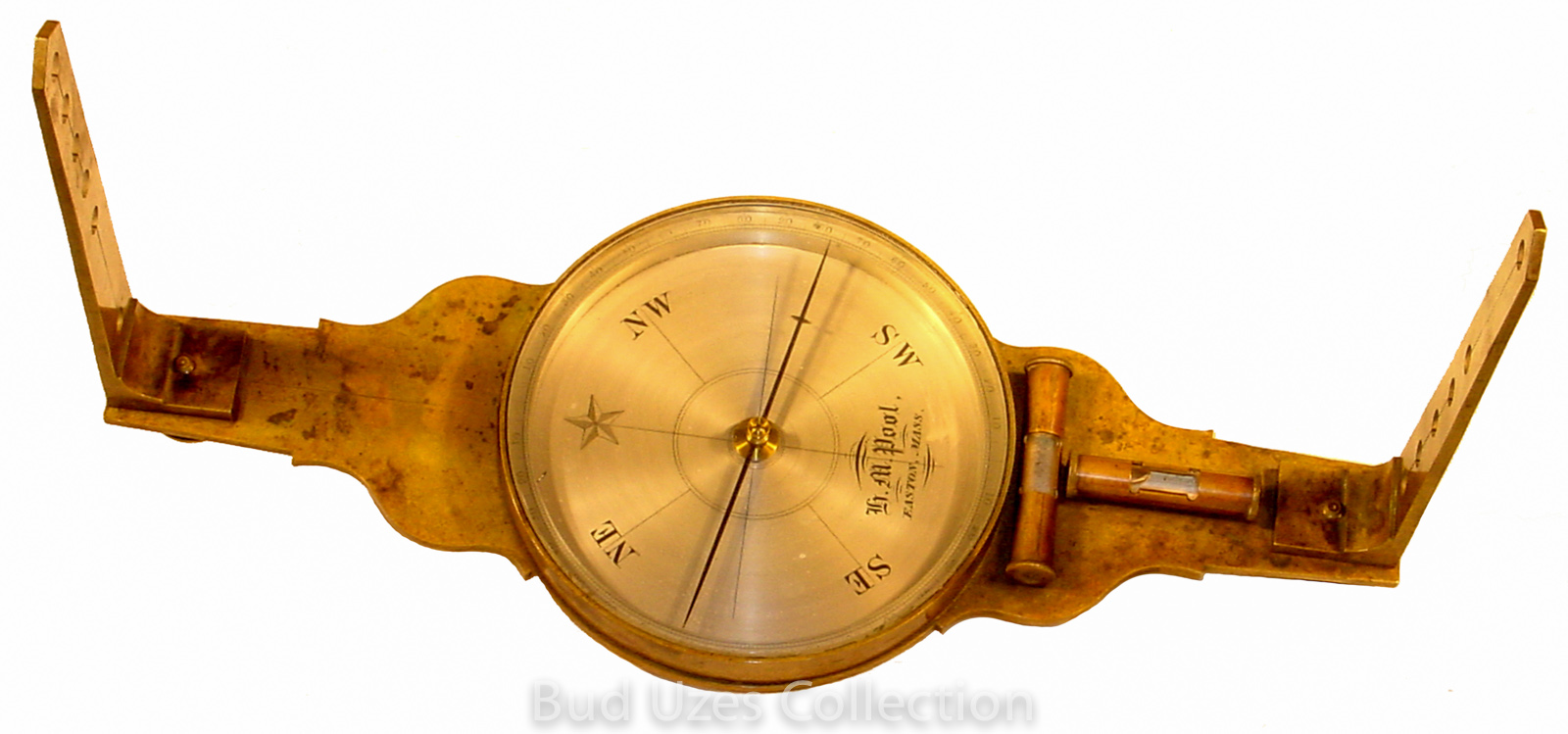
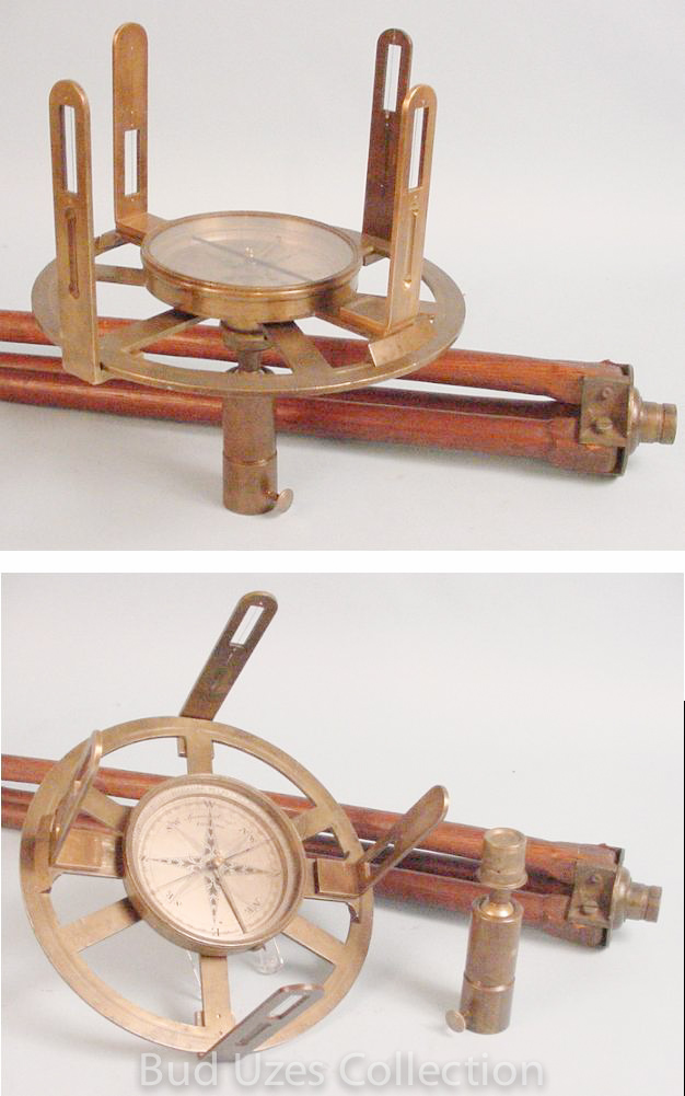
Surveyor's Plain Compass, H.M. Pool, maker, Easton, Mass., c. 1850.
This instrument is 15" long, has sights 7.4" high, and a 5.1" needle. There is a brass cover for the compass box, all fitting into the original wood case. There are two spirit levels on the south arm located next to one another, and at right angles to each other. In January, 1992, an original Pool tripod complete with a ball & socket unit was purchased from Don Sanders in Marysville, Washington, for $235.
This compass is pictured at the top of page 25 in the 1980 illustrated price guide.
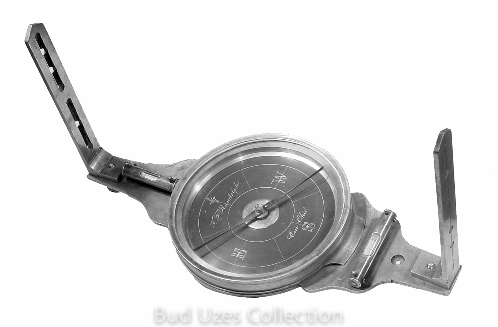
Surveyor's Vernier Compass, T.F. Randolph, maker, Cincinnati, Ohio, c. 1867.
This compass is 15.8" long, has sights 7.9" high, and a 6" magnetic needle. The compass dial is black. The vernier is located on the south arm outside the compass box. There are two spirit levels, one on each arm, both with clear glass and black lines. An open tapered hole in the south arm indicates the original position of a tally counter, now missing. An illustration of this exact instrument appears on pp. 26 of the 1889 edition of Thomas Bagot's A Manual of Plane Surveying. That print shows the same open tapered hole as the present instrument, together with an underside knob for changing the count.
Hedley Mining Dial, J. Casartelli & Son, Manchester, England, S/N 847, c. 1900
On the upper face it reads "Patent Mining Dial" then the number “847”, and at the bottom it reads "J.Casartelli & Son, Manchester". There are 4½” high folding sights on both ends and level vials in both directions (one is broken). The sighting arm is 12¾” long with a 5” magnetic needle. Outside of the fully divided circle is a vernier that enables readings to one minute on the inner degree scale. The compass still works and includes the base mount.
The Hedley mining dial was patented to John Hedley in 1850 and initially produced by John Davis & Son, Derby. The particular feature was the ability of the sighting arm to be elevated or lowered so as to take directional readings to targets at different elevations. Some dials also have a side-mounted graduated arc for measuring the vertical angle but most of those seen made by Casartelli do not. The dating is uncertain with little information available about when the Casartelli father/son name was in use.
Improved Miner’s Compass, John Hale, Scranton, PA, S/N 68, c. 1885
This instrument was invented and apparently produced by John Hale, and patented by him on March 10, 1885 as patent number 313,494. It was specifically adapted for use in mines in lieu of the miner’s compasses then employed. It is very much like a circumferentor except that it has only a single set of sights. Horizontal angles can be read independently of the needle on the outer divide circle of 10 ¾ inches diameter. The sights are 7 ¾” tall and the magnetic needle is 2.8” long There are two spirit levels both full of fluid.
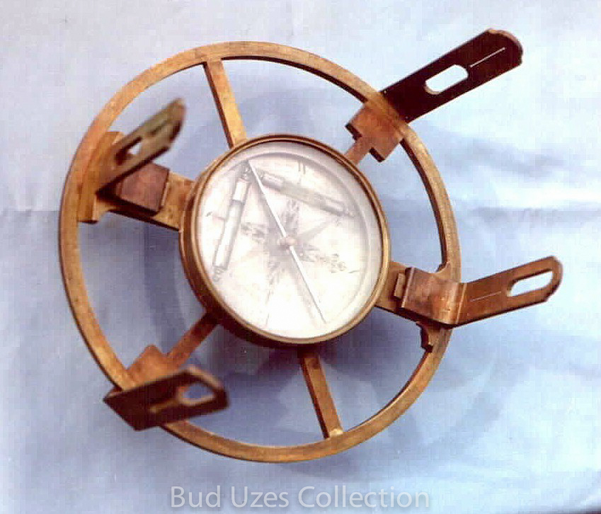
Mountain & Mining Vernier Compass, W. & L.E. Gurley Co., Troy, NY, c. 1900.
This is a one-of-a-kind size Gurley Mountain & Mining Vernier Compass especially built for both portability and sighting steep vertical angles. It was probably either a special order from the Gurley factory or a prototype of a new design considered by them but not put into production. The horizontal sighting arm is 9" long and the magnetic needle is 4 3/4" long. It has folding sight vanes that are an extraordinary 9 inches long. This length allows inclined sights of 38º where the conventional large vernier compass is capable of only 22º.
Single Vernier Railroad Compass, W. & L.E. Gurley Co., c. 1900
The single vernier railroad compass was produced by Gurley from the 1860’s to about 1915. They differ from the conventional vernier compass in that it has a divided horizontal circle that allows horizontal angles to be measured as in the transit instrument. Gurley made these with either one or two verniers, this being the smaller of the two. The needle is 5 ½” long. Complete with wood case.
Chains
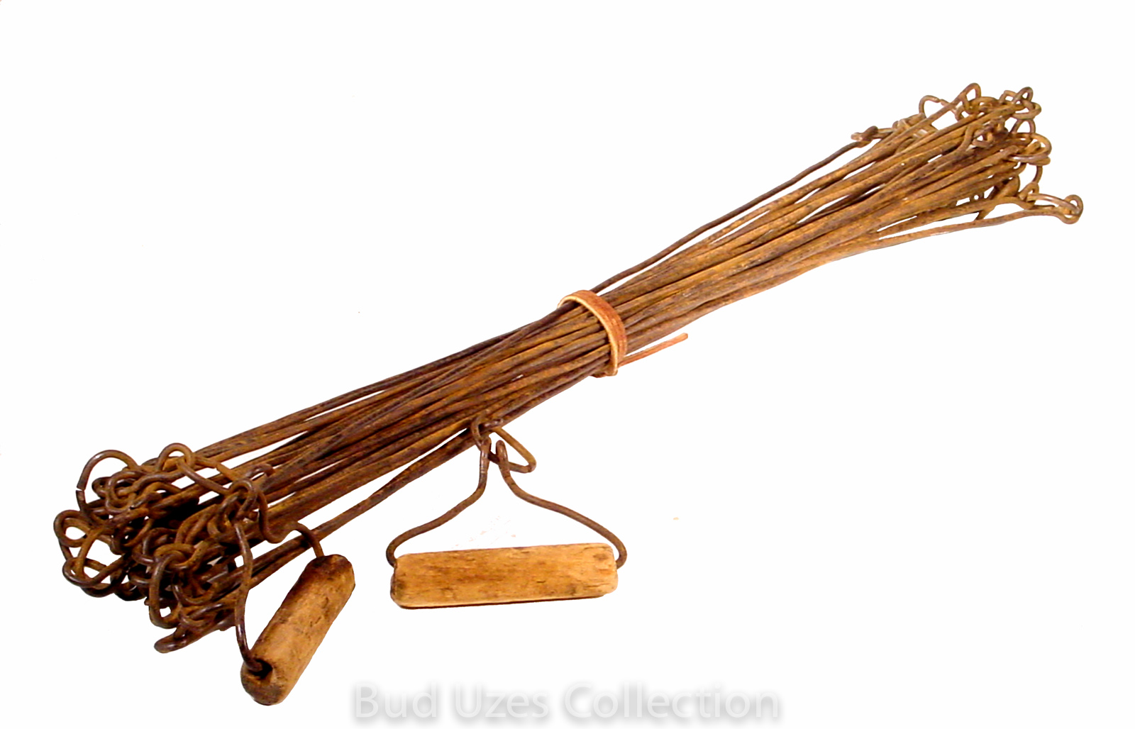
Two-pole Wing Chain, unsigned, c. 1760.
This iron chain has 40 links in two poles and is the pattern invented by Vincent Wing during the 1660's. It is first described by Wing in his 1664 book Geodaetes Practicus - Art of Surveying. . The metal has many carbon impurities in it suggesting a very old date.
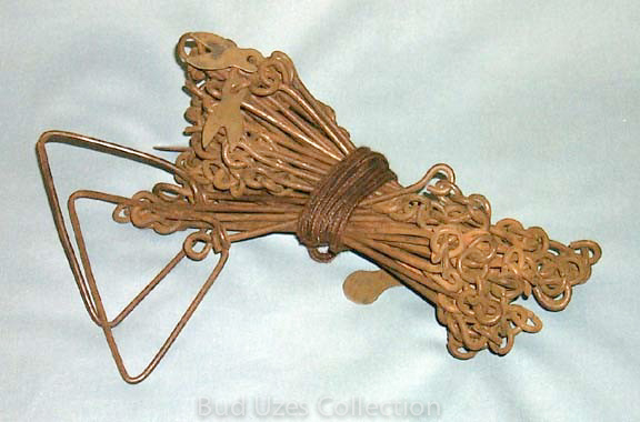
Vara Link Chain, unsigned, c. 1847.
This iron chain is 12 varas long with each link being one-half vara long. It was likely shortened from a 20 vara chain to accommodate the U.S. system of measure and is now 33 feet, or two-poles long. The handles are round iron rings of unequal size.
Four-pole Link Chain w/wood handles, unsigned, c. 1830.
This is a very rare pattern of link chain. The 32 links are each one-eighth pole long (24 3/4"). This variety is described in Vincent Wing's Geodaetes Practicus - Art of Surveying, page 215, published in 1664 and there is little information for determining the age of this example.
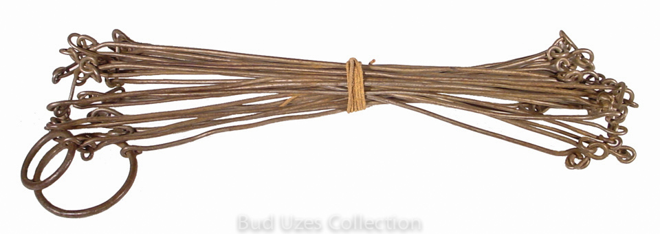
Two-pole Gunter Chain, unsigned, c. 1820.
This chain is of iron wire with rings pressed closed. The handles are triangular in shape and of the same wire as the links. It is complete with 4 brass tally tags with either one or two points, and has a circular brass tag at the midpoint. There is also a large swivel in the link next to the midpoint.
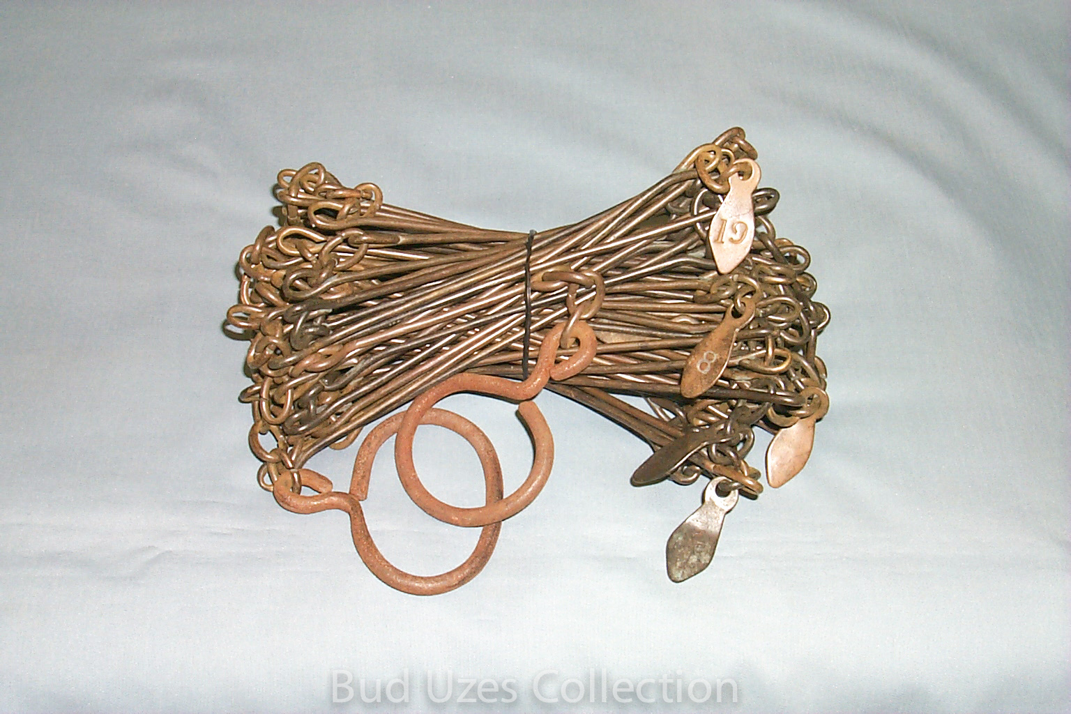
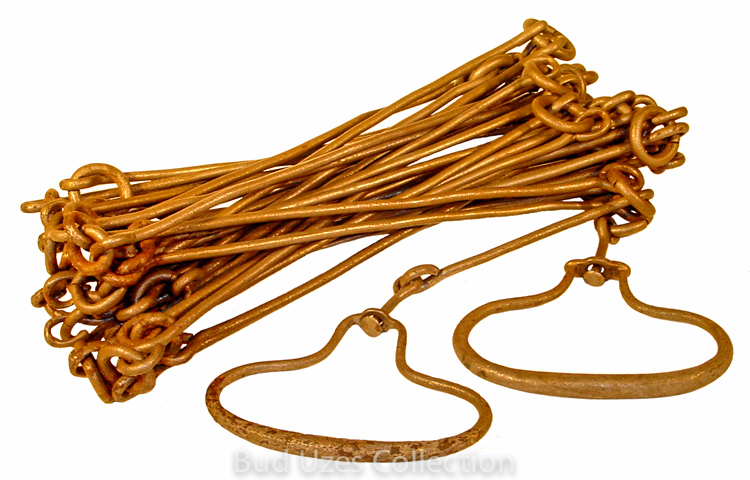
20-Yard Link Chain, unsigned, c. 1850.
This chain is of darkened brass wire with rings pressed closed. The handles are iron and of unequal size. There are 7 of the original 19 brass tally tags remaining. There are 80 nine-inch links connected by either one, two or three rings.
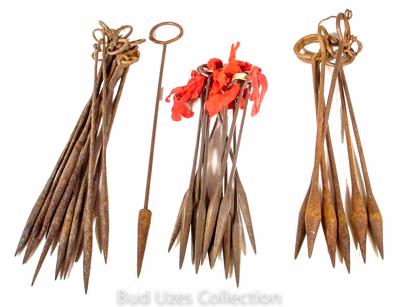
Assortment of 29 total Drop Pins (Chaining), unsigned, c. 1850 to 1900.
These are the type of weighted chaining pins that were specified for use in U.S. public lands surveys. They are weighted at the bottom so they will drop vertically when dropped for a position in the air. There are two complete sets of 11 pins, 6 of another variety, and a single example.
Plumb Bobs
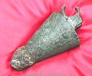
Ancient Egyptial Plumb Bob, unsigned, c. 250 B.C.
The plumb bob has a very ancient, corroded appearance and weighs 7 ounces. A small hinged loop at the top is broken and missing a segment of metal. A glob of corroded material covers the pointed bottom tip. The artifact is pictured on page 10 in the February-March, 1986 issue of P.O.B. Journal, Vol. 11, No. 3.
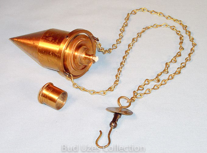
Mining Plummet Lamps, Heller & Brightly, maker, Philadelphia, PA.
This is a mining plummet lamp obtained in 1983 from the remnants at the Heller & Brightly factory after it was closed. Brand new condition - never sold.
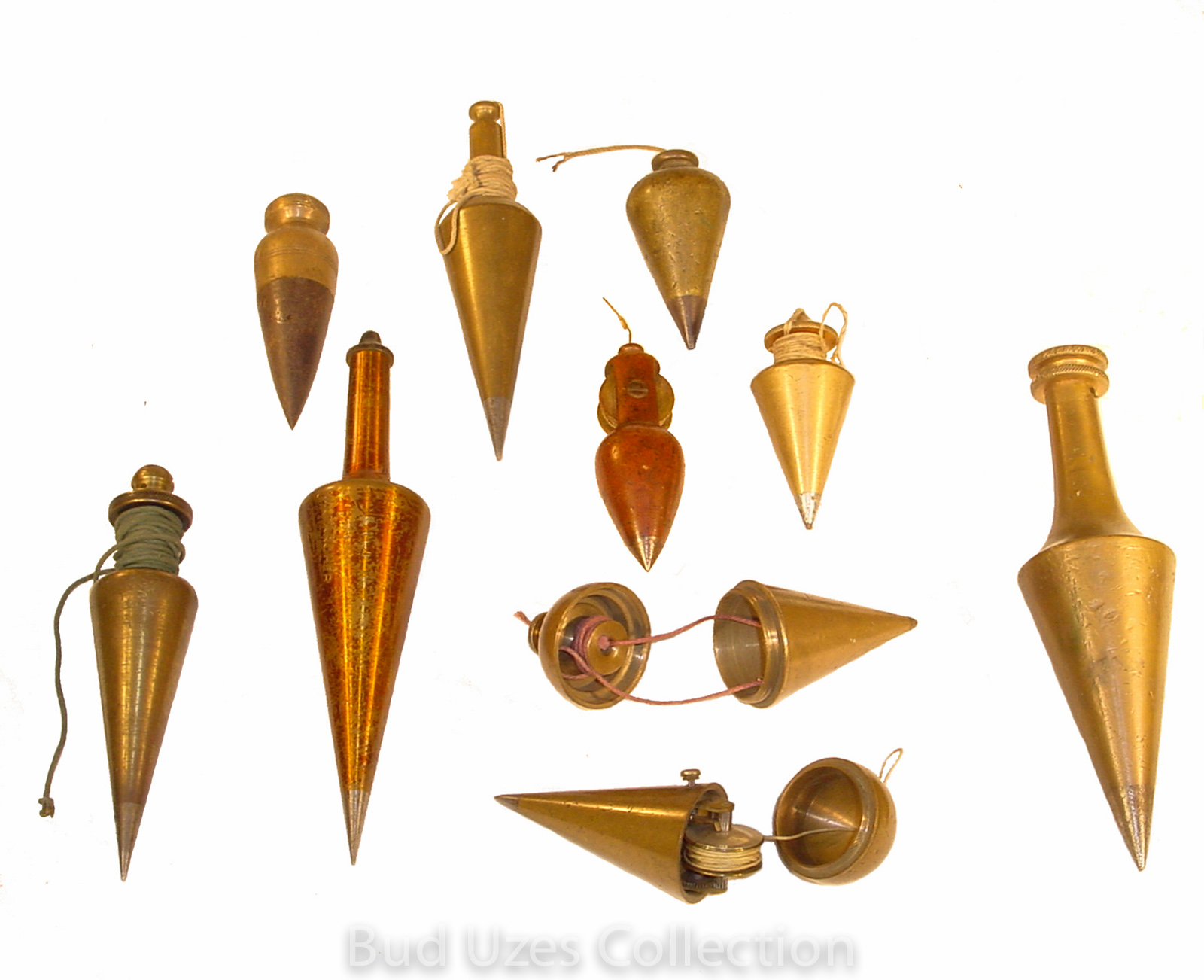
Assorted Bobs Plus a Rare Martin's Automatic Plumb Bob, Thompson Balance Co., maker, Denver, CO, c. 1905.
The above pic shows some of my dad's favorite plumb bobs. His all-time favorite was the Mrtin's automatic windup version at the bottom of the pic. It is 4" long and 1½" diameter, weighing 9 ounces. It has an internal spring wind-up that is operated by a push button.
Surveying Books
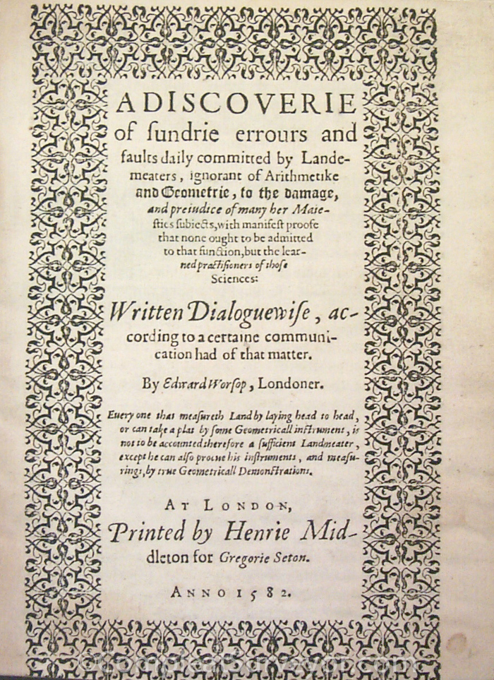
WORSOP, EDWARD, A DISCOVERIE OF SUNDRIE ERROURS AND FAULTS COMMITTED BY LANDE-MEATERS…(1582)
VERY RARE. FROM C.E. KENNEY COLLECTION, and signed by KENNEY (stating that this is the rarest English language surveying Book); ONE COPY AT YALE. Missing some pages at the end of the book. Older rebinding.
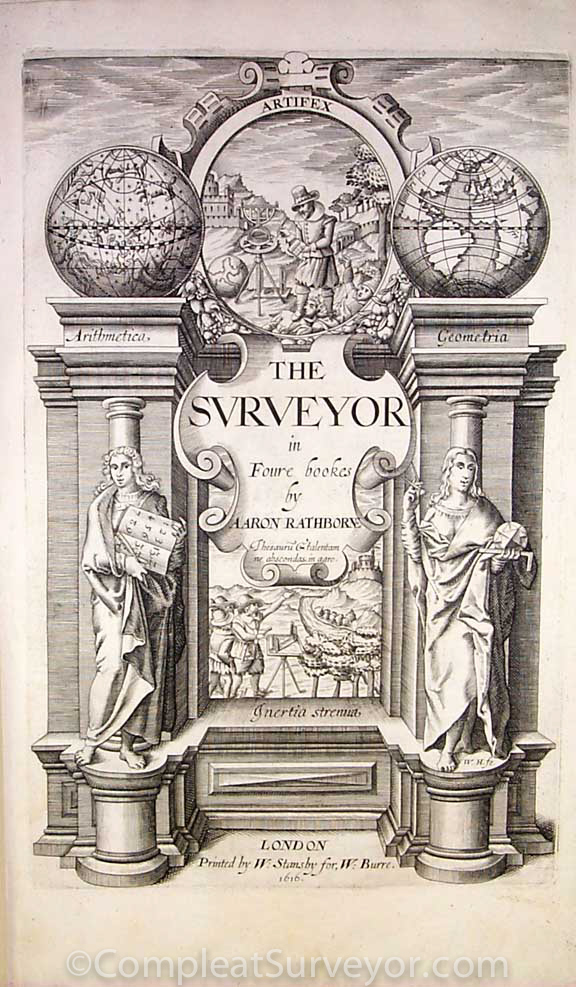
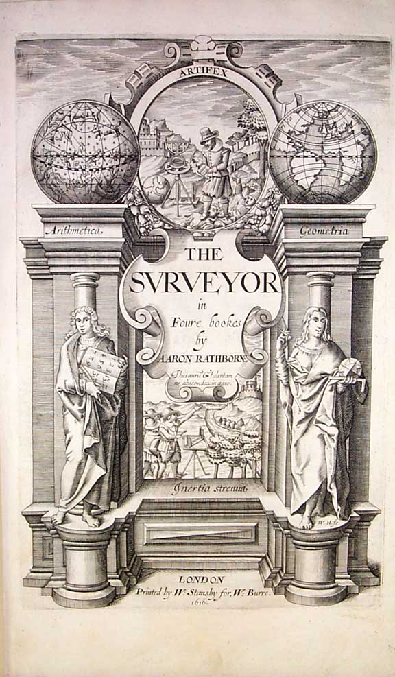
Rathborne, Aaron, The Surveyor in Foure Bookes, (London, 1616), 228 pages.
This is one of the all-time classics in surveying literature and set the stage for books that would follow for over 200 years. It contains much history on the manor system in addition to surveying fundamentals. The title page shows instruments of the period including an elaborate theodolite.
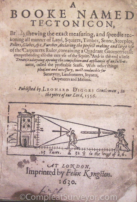
DIGGES, LEONARD, A BOOKE NAMED TECTONICON (1630)
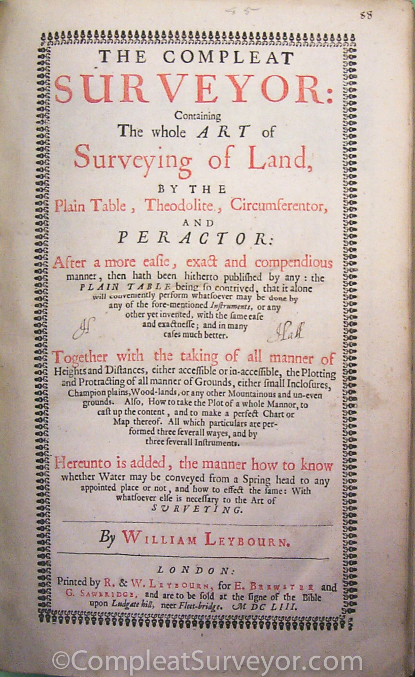
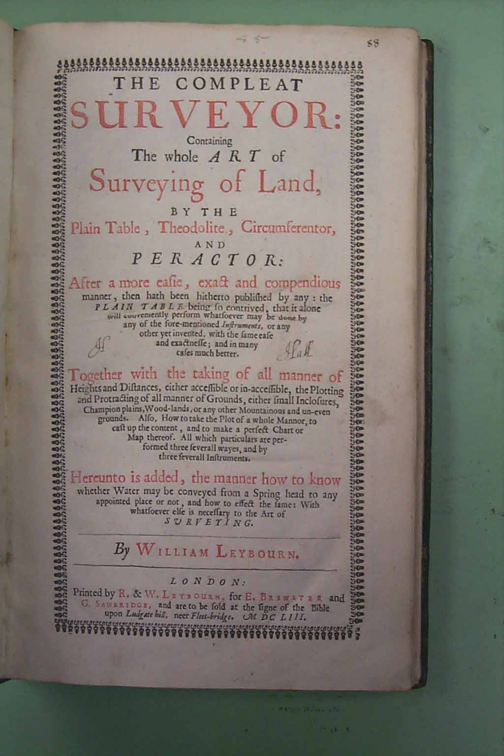
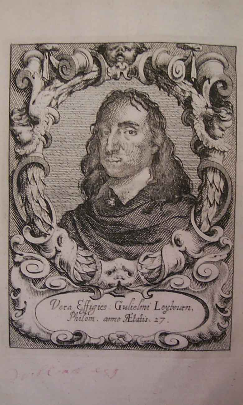
Leybourn, William, The Compleat Surveyor: Containing The whole Art of Surveying of Land, by the Plain Table, Theodolite, Circumferentor, and Peractor. (London, 1653), 279 pages with numerous illustrations, diagrams throughout and a portrait of the young Leybourn.
This was a major work of the period and was reprinted numerous times with the 5th edition of 1722 being substantially expanded upon by Samuel Cunn. The Cunn version included a number of fancied surveying illustrations of which some have been reprinted in recent times and at times incorrectly credited to the 1653 edition. Each edition of the book was larger in content and substance and brought the work to a standard that exceeded most others of the time.
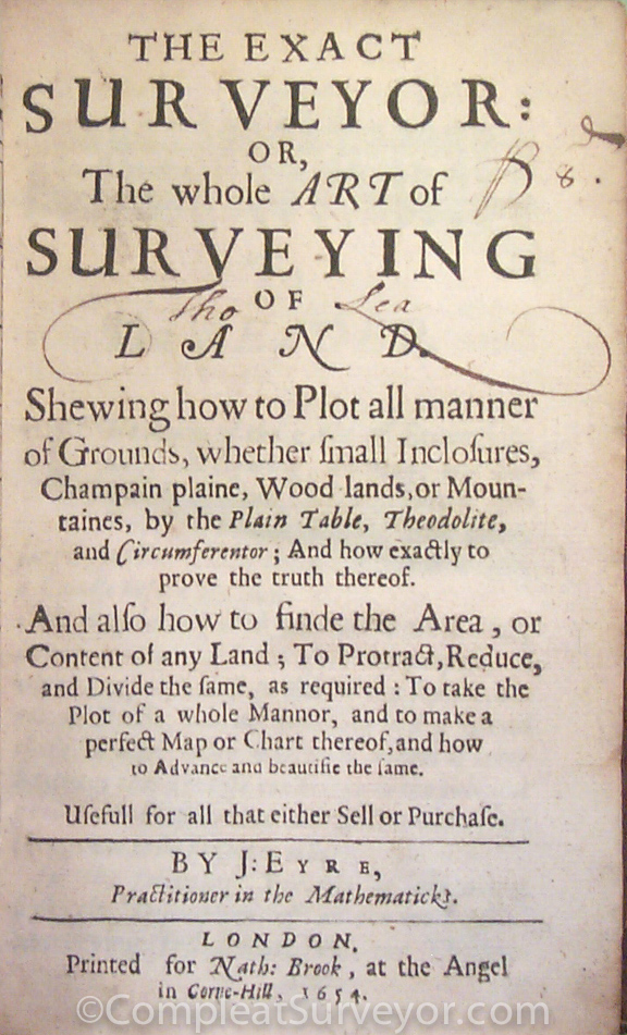
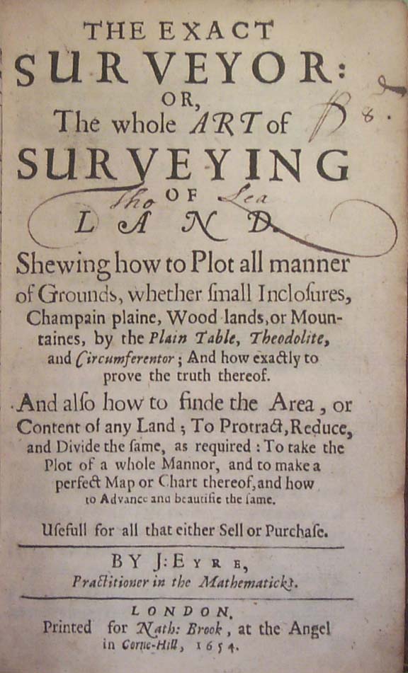
Eyre, J., The Exact Surveyor: or, The whole Art of Surveying of Land, (London, 1654), 224 pages.
This is a pocket size work that includes use of the plain table, theodolite and circumferentor. It also instructs on how to plot maps, calculate area, divide land, and account for the difference in length between the statutory and customary pole.
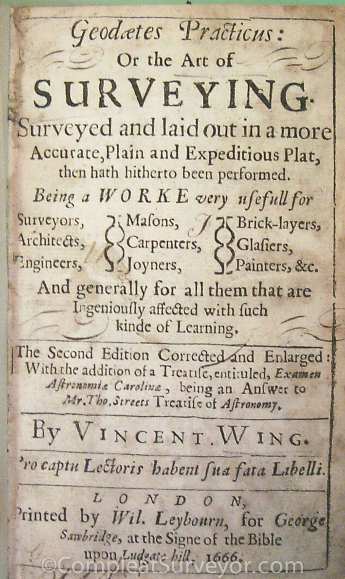
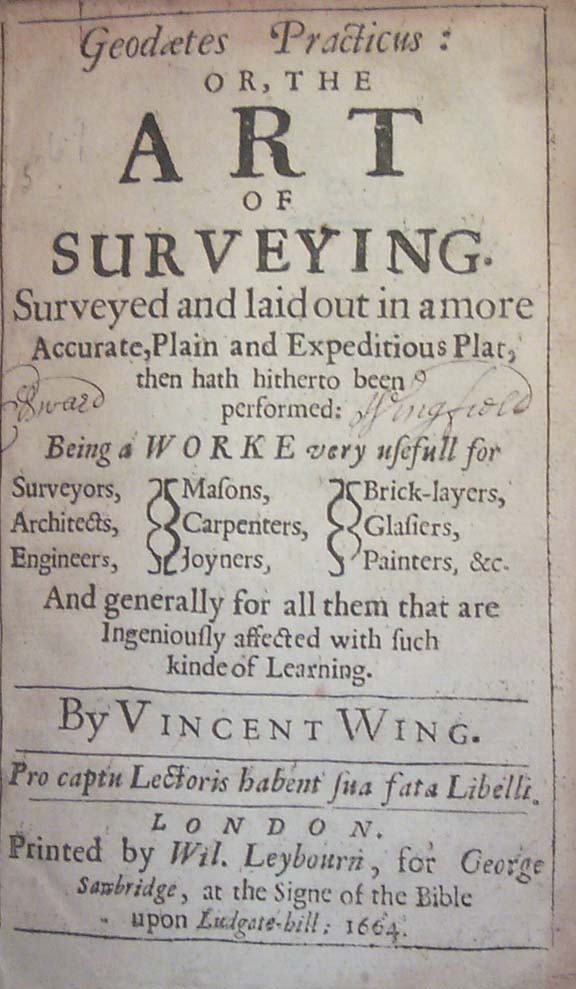
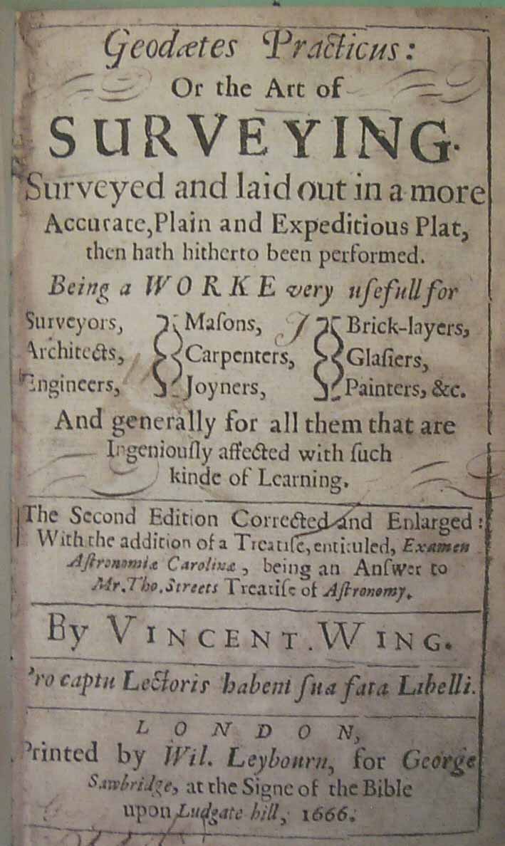
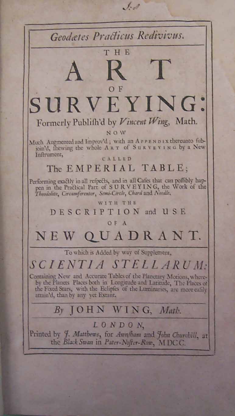
Wing, Vincent, Geodaetes Practicus: or, The Art of Surveying, Surveyed and laid out in a more Accurate, Plain and Expeditious Plat, then hath hitherto been performed.(London, 1666), 325 pages.
Wing is the designer of the 40-link two-pole chain that he stresses the value of when surveying tracts in rods or poles. The work is small in size and intended for use as a pocket book in the field. Almost all copies of the 1666 2nd edition were burned in the great London fire and only 3 are known to survive today. The fire damage is mentioned in William Leybourn's own 1674 surveying book, noting that Leybourn was the publisher of Wing's books. The imposing and much larger 3rd edition was published in 1700 by Vincent's nephew, John Wing.
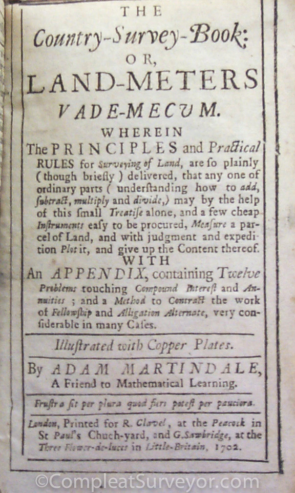
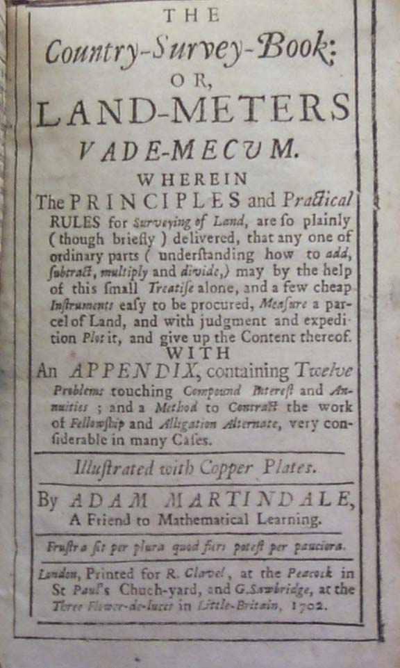
Martindale, Adam, The Country-Survey-Book: or, Land-Meters Vade-Mecvm, (London, 1682, 1702), 234 pages illustrated with copper plates.
This is a pocket size book that focuses on surveying with the chain and use of the plain table. It is intended for youths who prefer a smaller and less expensive work. A number of subsequent printings were made into the 18th century.
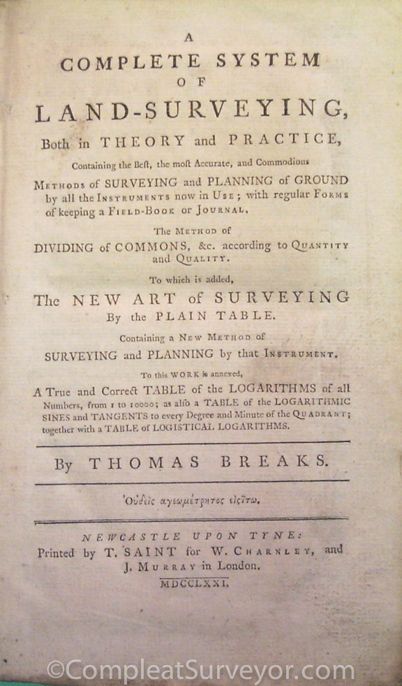
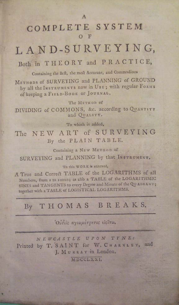
Breaks, Thomas, A Complete System of Land-Surveying, Both in Theory and Practice, Containing the Best, the most Accurate, and Commodious Methods of Surveying and Planning of Ground by all the Instruments now in Use; with Regular Forms of keeping a Field-Book or Journal, (Newcastle-upon-Tyne, 1771), 593 pages plus 17 folding plates.
This is a monumental work that is head and shoulders above others of the period although probably too advanced for the average surveyor of that period. It is comprised of 11 sub-books and includes information on the improved theodolite with spirit level and nonius, plane table, sector, chain and perambulator.
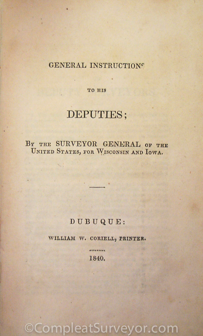
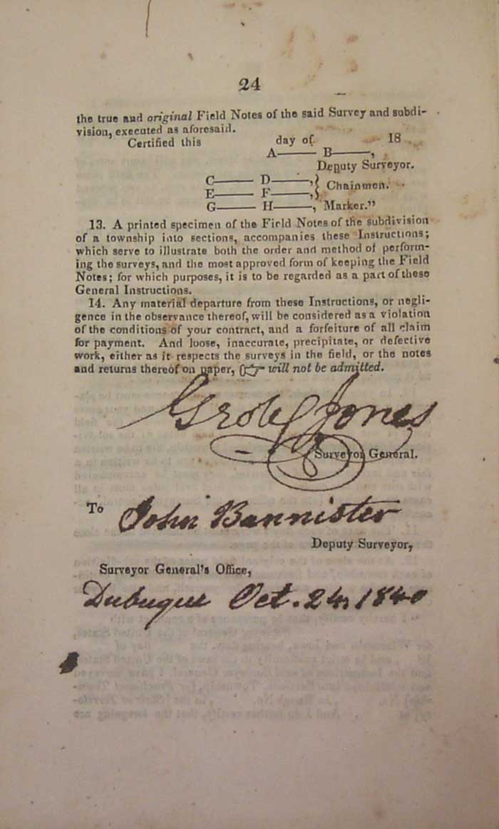
General Instructions to the Deputies…..George W. Jones, Surveyor General for Wisconsin and Iowa, issued instructions in 1840 for the survey of the public lands in that district. They are very similar to, and in most cases repeat word for word the 1833 Surveyor General's instructions for the states of Ohio, Indiana, and the Territory of Michigan. It is interesting to note that in both the 1833 and 1840 instructions, the method for determining the variation of the compass is "extracted from Flint's Treatise on Surveying." It is stated as perhaps "the most convenient and best adapted to the service in the field."
© 2020 Russ Uzes/Contact Me